Hyundai Tucson: Intake And Exhaust System / EGR Cooler
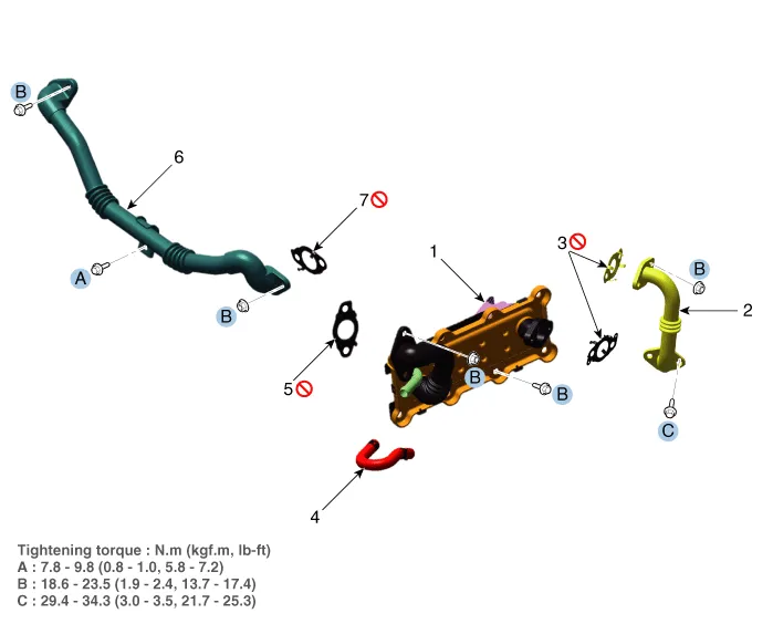
1. EGR cooler
2. EGR cooler pipe A
3. EGR cooler pipe A gasket
4. EGR cooler hose
5. EGR cooler pipe B gasket
6. EGR cooler pipe C
7. EGR cooler pipe C gasket

• Be careful not to damage the parts located under the vehicle (floor under cover, fuel filter, fuel tank and canister) when raising the vehicle using the lift.(Refer to General Information - "Lift and Support Points")
1.Disconnect the negative battery terminal.
2.Remove the engine cover.(Refer to the Engine And Transaxle Assembly - "Engine Cover")
3.Remove the air duct and air cleaner assembly.(Refer to the Intake And Exhaust System - "Air Cleaner")
4.Remove the engine room under cover.(Refer to the Engine And Transaxle Assembly - "Engine Room Under Cover")
5.Drain engine coolant by loosening the drain plug.(Refer to the Cooling System - "Coolant")
6.Remove the front muffler.(Refer to the Intake And Exhaust System - "Muffler")
7.Remove the exhaust manifold.(Refer to the Intake And Exhaust System - "Exhaust Manifold")
8.Remove the water inlet pipe.(Refer to the Cooling System - "ITM")
9.Remove the EGR cooler (A).
Tightening torque: 18.6 - 23.5 N.m (1.9 - 2.4 kgf.m, 13.7 - 17.4 lb-ft)
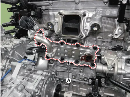

• Do not reuse the EGR cooler gasket.
10.Install in the reverse order of removal.

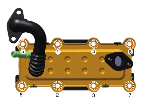
• When installing the EGR cooler, tighten the bolts with pre-torque first and then tighten the bolts with the specified torque as the sequence shown.
11.Fill engine coolant.(Refer to the Cooling System - "Coolant")

• Be sure to fill coolant following the ITM coolant filling method.
1.Disconnect the negative battery terminal.
2.Remove the engine cover.(Refer to the Engine And Transaxle Assembly - "Engine Cover")
3.Remove the air intake hose.(Refer to the Intake And Exhaust System - "Air Cleaner")
4.Remove the engine room under cover.(Refer to the Engine And Transaxle Assembly - "Engine Room Under Cover")
5.Drain engine coolant by loosening the drain plug.(Refer to the Cooling System - "Coolant")
6.Remove the ITM.(Refer to the Cooling System - "ITM")
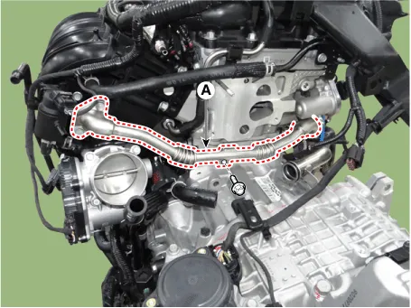
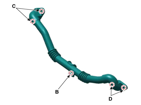
7.Remove the EGR cooler pipe C (A).
Tightening torque:Bolt (B) : 7.8 - 9.8 N.m (0.8 - 1.0 kgf.m, 5.8 - 7.2 lb-ft)Bolt (C) : 18.6 - 23.5 N.m (1.9 - 2.4 kgf.m, 13.7 - 17.4 lb-ft)Nut (D) : 18.6 - 23.5 N.m (1.9 - 2.4 kgf.m, 13.7 - 17.4 lb-ft)
8.Install in the reverse order of removal.
9.Fill engine coolant.(Refer to the Cooling System - "Coolant")

• Be sure to fill coolant following the ITM coolant filling method.
 Exhaust Manifold
- Components
1. Exhaust manifold 2. Exhaust manifold gasket3. Exhaust manifold stay
- Removal and installation
• Be careful not to damage the parts located under the ...
 Muffler
- Removal and Installation
• Be careful not to damage the parts located under the vehicle
(floor under cover, fuel filter, fuel tank and canister) when raising
the vehicle ...
Other information:
Hyundai Tucson (NX4) 2022-2026 Owner's Manual: Tires and Wheels
WARNING
Tire failure may cause loss of vehicle
control and result in a collision. To
reduce risk of serious injury or death:
Inspect your tires monthly for
proper inflation as well as wear
and damage.
The recommended cold tire
pressure for your vehicle can be
found in this man ...
Hyundai Tucson (NX4) 2022-2026 Service Manual: Troubleshooting
- Troubleshooting
SymptomPossible causeCountermeasure
Wind noise around the doorArise the gap on weatherstripReplace weatherstrip
Water leaks from panorama sunroofMiss install of panorama sunroof frame weather strip and deformingReplace
seal breakageFill with sealant
Wind noise on Panorama Su ...
