Hyundai Tucson: Engine Control System / Oil Temperature Sensor (OTS)
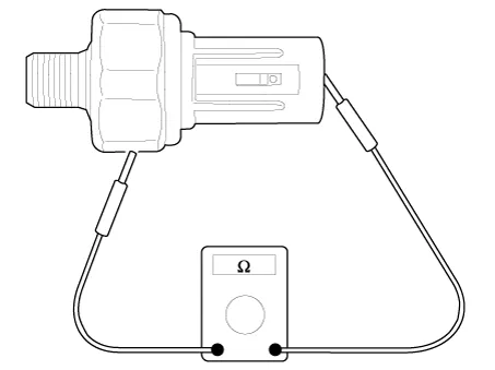
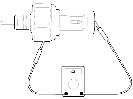
| Temperature | Resistance (kΩ) | |
| °C | °F | |
| -40 | -40 | 125.53 - 136.70 |
| -30 | -22 | 93.26 - 104.65 |
| -20 | -4 | 63.89 - 71.23 |
| -10 | 14 | 41.80 - 46.52 |
| 0 | 32 | 26.83 - 30.07 |
| 10 | 50 | 17.13 - 19.23 |
| 20 | 68 | 11.13 - 12.48 |
| 25 | 77 | 9.00 - 10.11 |
| 30 | 86 | 7.369 - 8.279 |
| 40 | 104 | 4.89 - 5.50 |
| 50 | 122 | 3.34 - 3.76 |
| 60 | 140 | 2.32 - 2.61 |
| 70 | 158 | 1.63 - 1.84 |
| 80 | 176 | 1.17 - 1.32 |
| 90 | 194 | 0.86 - 0.97 |
| 100 | 212 | 0.64 - 0.72 |
| 110 | 230 | 0.48 - 0.54 |
| 120 | 248 | 0.37 - 0.41 |
| 130 | 266 | 0.28 - 0.32 |
| 140 | 284 | 0.22 - 0.25 |
| 150 | 302 | 0.17 - 0.20 |
| 160 | 320 | 0.14 - 0.16 |
1.In the engine control system, failure can be quickly diagnosed by using the diagnosis tool.
(1)Self diagnosis : Checking failure and code number (DTC).
(2)Current data : Checking the system input/output data state.
(3)Actuation test : Checking the system operation condition.
(4)Additional function : Controlling other features including system option setting and zero point adjustment.
1.Check the continuity between the terminal and the body using an ohmmeter. If the continuity fails, replace the switch.
2.Press the inside of the oil hole with a slender rod etc. and check the continuity between the terminal and the body. Change the switch if it is energized while being pressed.
3.If the pressure (0.5kg/cm2) is not energized when applied through the oil hole, the switch is functioning normally. Check for air leaks, and if there is any leakage, replace the switch as the diaphragm is damaged.

• Be careful not to damage the parts located under the vehicle (floor under cover, canister, fuel tank) when raising the vehicle using the lift.(Refer to General Information - "Lift and Support Points")
1.Disconnect the battery negative (-) terminal.
2.Remove the engine room under cover.(Refer to Engine Mechanical System - "Engine Room Under Cover")
3.Drain the enigne oil.(Refer to Engine Mechanical System - "Engine Oil")
4.Remove the intake manifold.(Refer to Engine Mechanical System - "Intake Manifold")
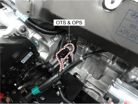
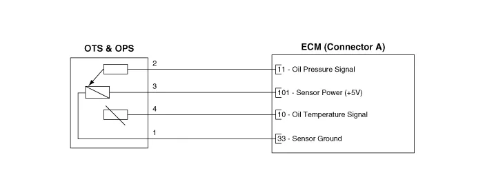
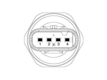
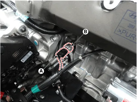
5.Disconnect the connector (A) and then remove the sensor (B).
Tightening torque :35.3 - 38.2 N.m (3.6 - 3.9 kgf.m, 26.0 - 28.2 lb-ft)
1.Install in the reverse order of removal.

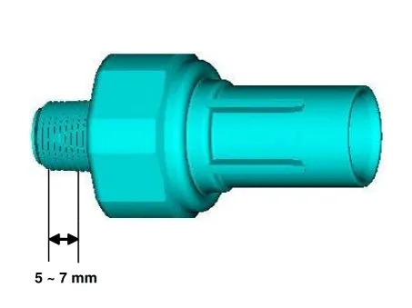
• Apply the sealant to the sensor.
Specification : TB2403Tickness : 0.2 - 0.4 mm (0.0079 - 0.0157 in.)
 Electric EGR Control Valve
- Description
The Electric EGR Control Valve is installed in between the EGR cooler
and the exhaust line and is a solenoid valve. This valve controls EGR
(Exhaust Gas Recirculation) amount by t ...
 Oil Pressure Sensor (OPS)
- Description
Continuous Variable Valve Timing (CVVT) system advances or retards the
valve timing of the intake and exhaust valve in accordance with the ECM
control signal which is calculated b ...
Other information:
Hyundai Tucson (NX4) 2022-2026 Service Manual: IMS Control Switch
- Components
- Removal
1.Disconnect the negative (-) battery terminal.
2.Remove the front door trim.(Refer to Body - "Front Door Trim")
3. Remove the IMS switch (A) after loosening mounting screws.
- Installation
1.Install the IMS switch.
2.Reassemble the front door trim.
3. ...
Hyundai Tucson (NX4) 2022-2026 Service Manual: Knock Sensor (KS)
- Description
Knocking is a phenomenon characterized by undesirable vibration and
noise and can cause engine damage. Knock Sensor (KS) is installed on the
cylinder block and senses engine knocking.When knocking occurs, the
vibration from the cylinder block is applied as pressure to the
pi ...
