Hyundai Tucson: Engine Control System / Oil Pressure Sensor (OPS)
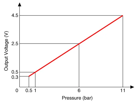
| Pressure | Output Voltage (V) [Vref=5V] | Initial Condition | |
| bar | [MPa (kgf/cm²)] | ||
| 0.5 | 0.05 (0.5) | 0.3 ± 0.06 | 0.3 ± 0.04 |
| 1 | 0.1 (1.0) | 0.5 ± 0.06 | 0.5 ± 0.04 |
| 6 | 0.6 (6.1) | 2.5 ± 0.06 | 2.5 ± 0.04 |
| 11 | 1.1 (11.2) | 4.5 ± 0.06 | 4.5 ± 0.04 |
1.In the engine control system, failure can be quickly diagnosed by using the diagnosis tool.
(1)Self diagnosis : Checking failure and code number (DTC).
(2)Current data : Checking the system input/output data state.
(3)Actuation test : Checking the system operation condition.
(4)Additional function : Controlling other features including system option setting and zero point adjustment.
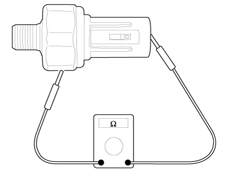
1.Check the continuity between the terminal and the body using an ohmmeter. If the continuity fails, replace the switch.
2.Press the inside of the oil hole with a slender rod etc. and check the continuity between the terminal and the body. Change the switch if it is energized while being pressed.
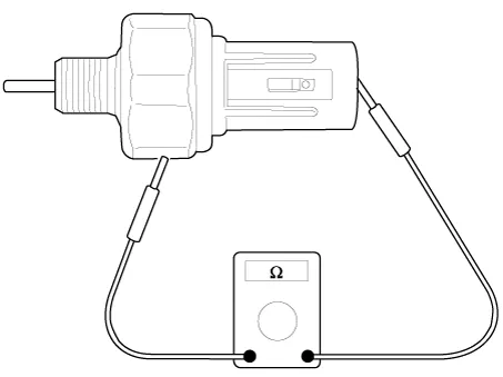
3.If the pressure (0.5kg/cm2) is not energized when applied through the oil hole, the switch is functioning normally. Check for air leaks, and if there is any leakage, replace the switch as the diaphragm is damaged.

• Be careful not to damage the parts located under the vehicle (floor under cover, canister, fuel tank) when raising the vehicle using the lift.(Refer to General Information - "Lift and Support Points")
1.Disconnect the battery negative (-) terminal.
2.Remove the engine room under cover.(Refer to Engine Mechanical System - "Engine Room Under Cover")
3.Drain the enigne oil.(Refer to Engine Mechanical System - "Engine Oil")
4.Remove the intake manifold.(Refer to Engine Mechanical System - "Intake Manifold")
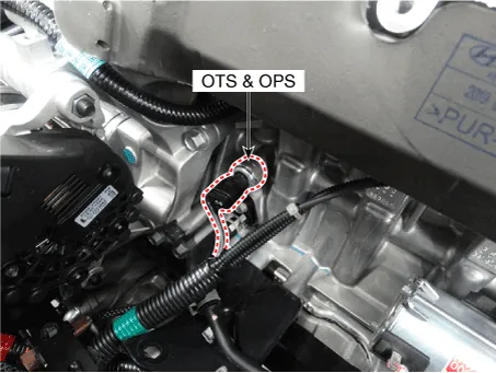
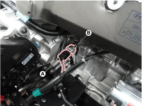
5.Disconnect the connector (A) and then remove the sensor (B).
Tightening torque :35.3 - 38.2 N.m (3.6 - 3.9 kgf.m, 26.0 - 28.2 lb-ft)
1.Install in the reverse order of removal.

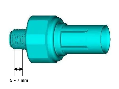
• Apply the sealant to the sensor.
Specification : TB2403Tickness : 0.2 - 0.4 mm (0.0079 - 0.0157 in.)
 Oil Temperature Sensor (OTS)
- Description
Continuous Variable Valve Timing (CVVT) system advances or retards the
valve timing of the intake and exhaust valve in accordance with the ECM
control signal which is calculated b ...
 Integrated Thermal Management Module (ITM)
- Description
Integrated Thermal Management Module (ITM) is a device that controls
the coolant flow rate according to coolant temperature. At initial
startup, the ITM quickly warms up the engin ...
Other information:
Hyundai Tucson (NX4) 2022-2026 Service Manual: Fuel Pressure Regulator
- Removal
1.Remove the fuel pump.(Refer to Fuel Delivery System - "Fuel Pump")
2.Disconnect the fuel sender connector (A).
3.Release the fixing hook (A) and then remove fuel sender (B) in the arrow direction.
4.Disconnect the fuel pump motor connector (A).
5.Remove the fixing pin (A) ...
Hyundai Tucson (NX4) 2022-2026 Owner's Manual: Starting the engine
A : Vehicle authentication pad (Wireless charging
pad)
1. After placing your registered card key
on the vehicle authentication pad
(wireless charging pad), depress the
brake pedal and press the Button Start
ignition switch button.
2. After start-up, the digital key data will
be autom ...
