Hyundai Tucson: Transfer Assembly / Front Wheel Transfer Assembly

ŌĆó Be careful not to damage the parts located under the vehicle (floor under cover, fuel filter, fuel tank and canister) when raising the vehicle using the lift.(Refer to General Information - "Lift and Support Points")
1.Remove the engine room under cover.(Refer to Engine Mechanical System - "Engine Room Under Cover")
2.Remove the front driveshaft assembly. [Right side](Refer to Driveshaft and Axle - "Front Driveshaft")
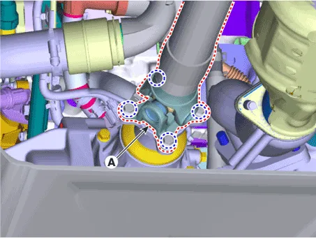
3.Remove the front propeller shaft assembly (A) from the transfer assembly.
Tightening torque :49.0 - 68.6 N.m (5.0 - 7.0 kgf.m, 36.2 - 50.6 lb-ft)
4.Remove the transfer case assembly.
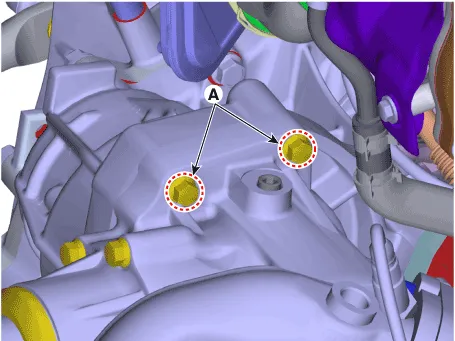
(1)Loosen the transafer assembly upper mounting bolts (A).
Tightening torque :60.8 - 65.7 N.m (6.2 - 6.7 kgf.m, 44.8 - 48.5 lb-ft)
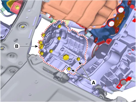
(2)Loosen the lower mounting bolts (A) and then removing the transfer case assembly (B).
Tightening torque :60.8 - 65.7 N.m (6.2 - 6.7 kgf.m, 44.8 - 48.5 lb-ft)

ŌĆó Be careful not to damage the parts located under the vehicle (floor under cover, fuel filter, fuel tank and canister) when raising the vehicle using the lift.(Refer to General Information - "Lift and Support Points")
1.Remove the engine room under cover.(Refer to Engine Mechanical System - "Engine Room Under Cover")
2.Remove the front drive shaft assembly. [Right side](Refer to Driveshaft and Axle - "Front Driveshaft")
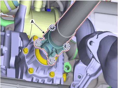
3.Remove the front propeller shaft assembly (A) from the transfer assembly.
Tightening torque :49.0 - 68.6 N.m (5.0 - 7.0 kgf.m, 36.2 - 50.6 lb-ft)
4.Remove the transfer case assembly.
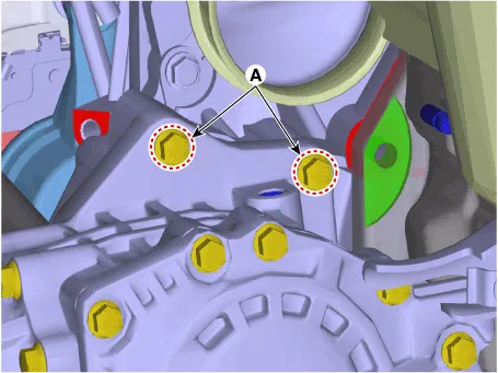
(1)Loosen the transafer assembly upper mounting bolts (A).
Tightening torque :60.8 - 65.7 N.m (6.2 - 6.7 kgf.m, 44.8 - 48.5 lb-ft)
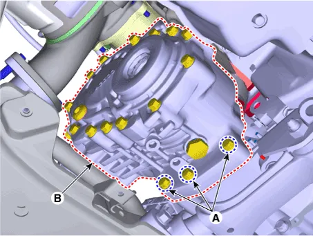
(2)Loosen the lower mounting bolts (A) and then removing the transfer case assembly (B).
Tightening torque :60.8 - 65.7 N.m (6.2 - 6.7 kgf.m, 44.8 - 48.5 lb-ft)
1.To install, reverse the removal procedures.

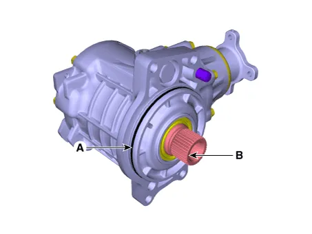
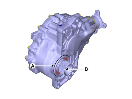
ŌĆó Be careful not to damage the O-ring (A). If the O-ring is damaged, replace with a new one.
ŌĆó Smear and cover splines (B) with molybdenum type high pressure grease.
GREASE SPL-1 equivalent (MS511-07)
[A Type]
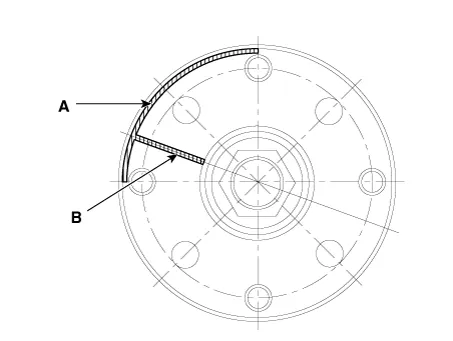
ŌĆó Install the propeller shaft to be near runout marking (Transfer assembly 1ea (A), propeller shaft 1ea (B) each other.
 Transfer Fluid
- Inspection
ŌĆó Transfer oil should be inspected and refilled every 60,000 km (40,000 mile) / 4 year.
ŌĆó Be careful not to damage the parts located under ...
 Oil Seal
- Component
[A Type]
1. Transfer Case2. Oil seal (Transaxle side)
[B Type]
1. Dust cover2. Oil seal #1 (Drive shaft side)3. Oil seal #2 (Drive shaft side)4. Oil seal #3 (Drive shaft si ...
Other information:
Hyundai Tucson (NX4) 2022-2026 Service Manual: Front Oil Seal
- Replacement
ŌĆó Be careful not to damage the parts located under the vehicle
(floor under cover, fuel filter, fuel tank and canister) when raising
the vehicle using the lift.(Refer to General Information - "Lift and
Support Points")
1.Remove the crankshaft damper pul ...
Hyundai Tucson (NX4) 2022-2026 Service Manual: Air Cleaner
- Removal and installation
Air Cleaner Assembly
1.Disconnect the battery negative terminal.
2.Remove the engine cover.(Refer to Engine And Transaxle Assembly - ŌĆ£Engine CoverŌĆØ)
3.Remove the air duct (A).
4.Remove the air cleaner assembly.(1)Disconnect the air flow sensor connector (A) ...
