Hyundai Tucson: Driveshaft Assembly / Front Driveshaft
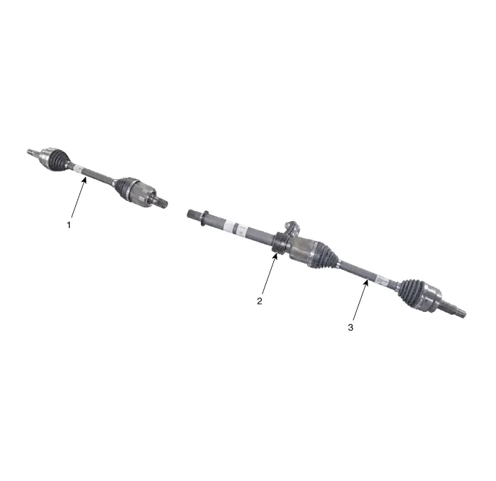
1. Front driveshaft (LH)
2. Inner shaft bearing bracket
3. Front driveshaft (RH)

• When lifting a vehicle using a lift, be careful not to damage the lower parts of the vehicle (floor under cover, fuel filter, fuel tank, canister).(Refer to General Information - "Lift and Support Points")
1.Loosen the front wheel nuts slightly.Raise the vehicle, and make sure it is securely supported.
2.Remove the front wheel and tire.(Refer to Suspension System - "Wheel")
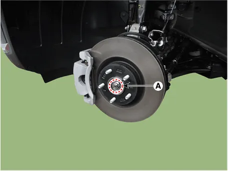
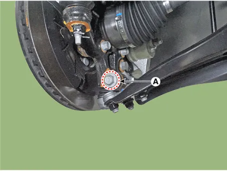
3.Loosen the caulking nut (A) from the front hub.
Tightening torque : 294.2 - 313.8 N.m (30.0 - 32.0 kgf.m, 217.0 - 231.5 lb-ft)

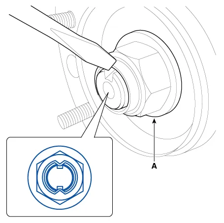
• The driveshaft lock nut (A) should be replaced with new ones.
• After installation driveshaft lock nut, stake the lock nut using a chisel and hammer as shown in the illustration below.
Caulking depth : 1.5 mm (0.591 in.)
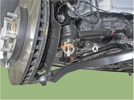
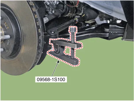
4.Loosen the tie rod end ball joint nut (A).
Tightening torque: 98.0 - 117.6 N.m (10.0 - 12.0 kgf.m, 72.3 - 86.7 lb-ft)
5.Remove the tie rod end ball joint using the SST (09568-1S100).
6.Loosen the front lower arm mounting bolt and nut (A).
Tightening torque: 98.0 - 117.6 N.m (10.0 - 12.0 kgf.m, 72.3 - 86.7 lb-ft)
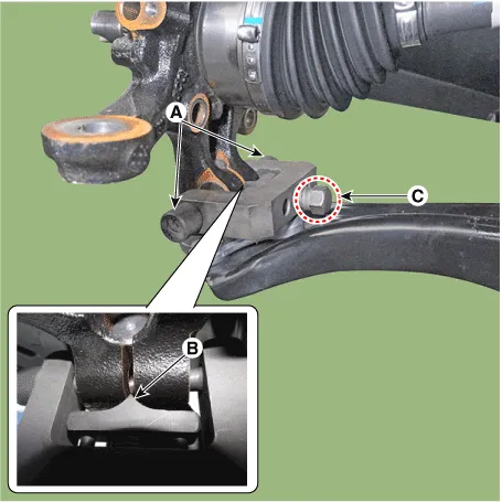
7.Remove the lower arm from the knuckle by using the SST (09568-4R100).
(1)Install the support bolt (A) from lower arm bolt hole.
(2)Install the support body (B) from front axle.
(3)Tighten the bolt (C).
8.Remove the drive shaft (A) from the front axle assembly (B).
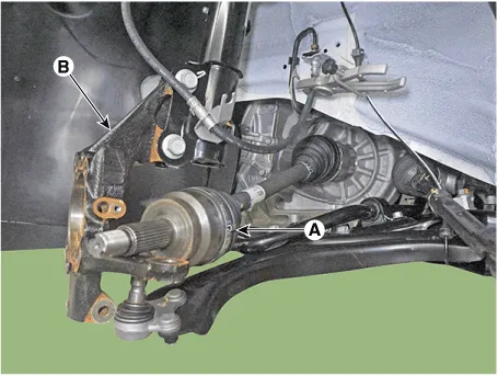
9.Remove the driver side drive shaft (B) using the pry bar (A).
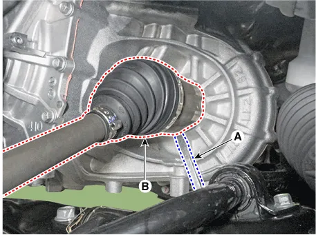

• Use a pry bar being careful not to damage the transaxle and joint.
• Do not insert the pry bar too deep, as this may cause damage to the oil seal.
• Do not pull the driveshaft by excessive force it may cause components inside the joint kit to dislodge resulting in a torn boot or a damaged bearing.
• Plug the hole of the transaxle case with the oil seal cap to prevent contamination.
• Support the driveshaft properly.
• Replace the retainer ring whenever the driveshaft is removed from the transaxle case.
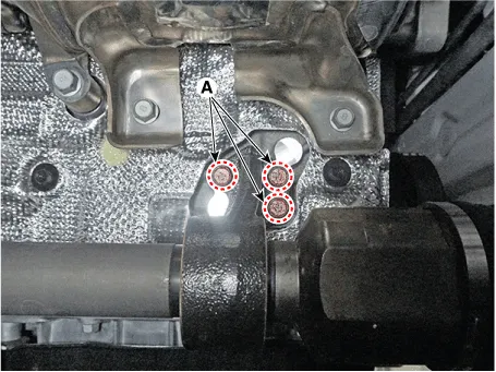
10.Remove the passenger side driveshaft after loosening the inner shaft mounting bolts (A).
Tightening torque: 49.0 - 68.6 N.m (5.0 - 7.0 kgf.m, 36.2 - 50.6 lb-ft)
1.To install, reverse the removal procedures.
2.Check the alignment.(Refer to Suspension System - "Alingment")

 Dynamic Damper
- Removal
1.Remove the front drive shaft.(Refer to Driveshaft Assembly - "Front Driveshaft")
2.Remove the trans axle side joint.(Refer to Driveshaft Assembly - "Transaxle Joint")
3.Remove the d ...
Other information:
Hyundai Tucson (NX4) 2022-2026 Service Manual: Repair procedures
- Removal
• Put on gloves to prevent hand injuries.
• Use seat covers to avoid damaging any surfaces.
1.Remove the liftgate trim.(Refer to Liftgate - "Liftgate Trim")
2.Remove the rear spoiler.(Refer to Body Side Molding - "Rear Spoiler")
3.Dis ...
Hyundai Tucson (NX4) 2022-2026 Service Manual: Rear Oil Seal
- Replacement
• Be careful not to damage the parts located under the vehicle
(floor under cover, fuel filter, fuel tank and canister) when raising
the vehicle using the lift.(Refer to General Information - "Lift and
Support Points")
1.Remove the Automatic Transaxle A ...
