
Hyundai Tucson: Body Electrical System / Power Door Locks
Components and Components Location
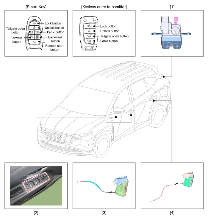
1. Liftgate lock actuator
2. Driver door moudle (DDM)
3. Front door lock actuator
4. Rear door lock actuator
Power Door Lock Actuators
1.Remove the front door trim.(Refer to Body - "Front Door Trim")
2.Disconnect the connectors from the actuator.
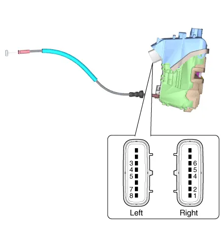
3.Check actuator operation by connecting power and ground according to the table.
| Pin | Description | |
| Driver | Panssenger | |
| 1 | - | M2 |
| 2 | - | M3 |
| 3 | COM | - |
| 4 | Lock/Unlock switch | AJAR |
| 5 | AJAR | Lock/Unlock switch |
| 6 | - | COM |
| 7 | M3 | - |
| 8 | M2 | - |
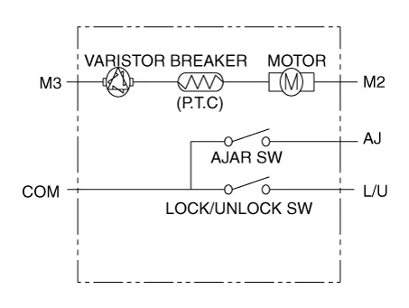


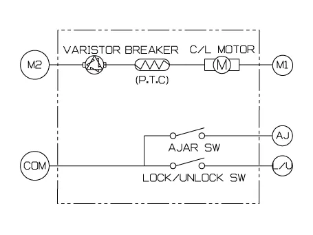
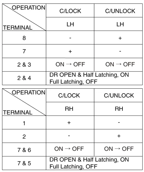
1.Remove the rear door trim.(Refer to Body - "Rear Door Trim")
2.Disconnect the connectors from the actuator.
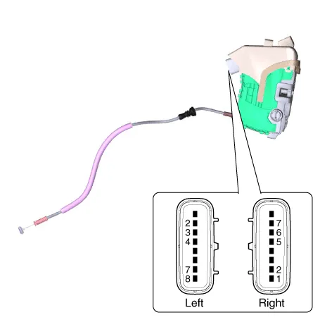
3.Check actuator operation by connecting power and ground according to the table.
| Pin | Description | |
| Driver | Panssenger | |
| 1 | - | M1 |
| 2 | COM | M2 |
| 3 | Lock/Unlock switch | - |
| 4 | AJAR | - |
| 5 | - | AJAR |
| 6 | - | Lock/Unlock switch |
| 7 | M2 | COM |
| 8 | M1 | - |
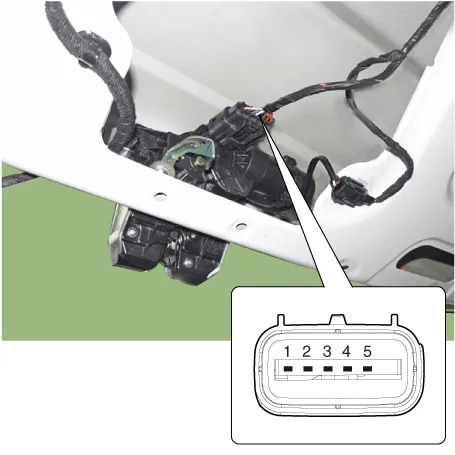
1.Remove the liftlgate trim.(Refer to Body - "Liftgate Trim")
2.Disconnect the connector from the actuator.
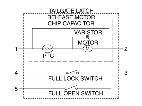
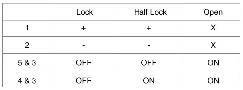
3.Check actuator operation by connecting power and ground according to the table.
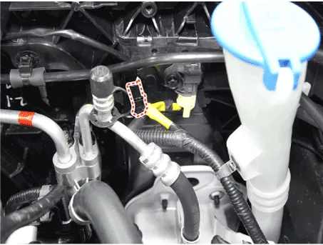
1.Disconnect the hood switch connector (A).
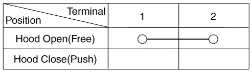
2.Check for continuity between the terminals and ground according to the circuit diagram.
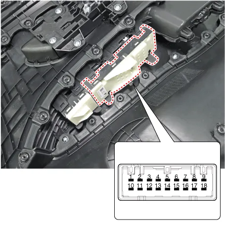
Power Door Lock Switch
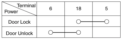
1.1. Check for continuity between the terminals. If there is an abnormality, replace the switch.
1.In the body electrical system, failure can be quickly diagnosed by using the vehicle diagnostic system.The diagnostic system provides the following information.
(1)Fault Code Searching : Checking failure and code number (DTC)
(2)Data Analysis : Checking the system input/output data state
(3)Actuation test : Checking the system operation condition
(4)S/W Management : Controlling other features including system option setting and zero point adjustment
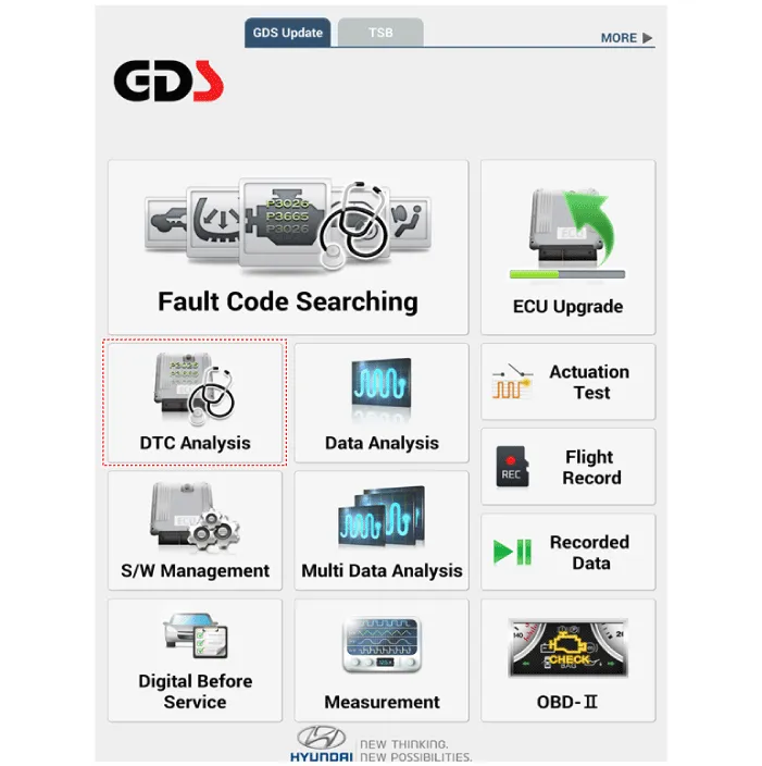
2.If diagnose the vehicle by diagnostic tool, select "DTC Analysis" and "Vehicle".
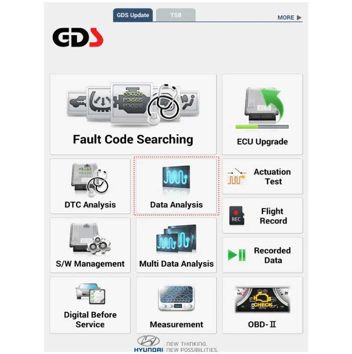
3.If check current status, select the "Data Analysis" and "Car model".
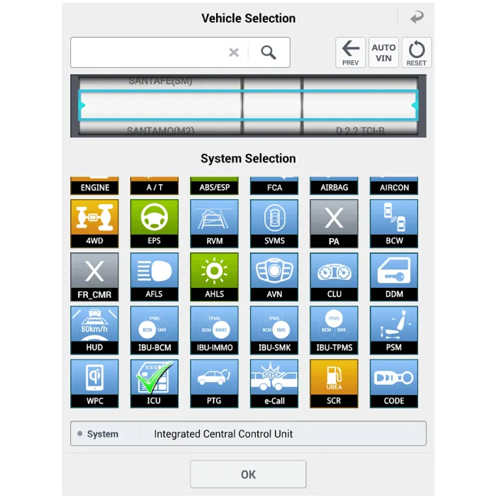
4.Select the 'ICU' to search the current state of the input/output data.
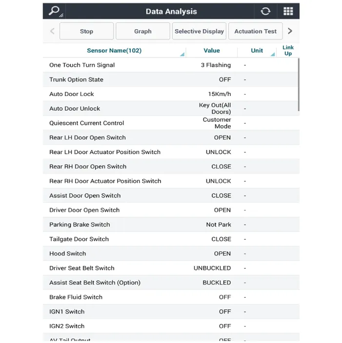
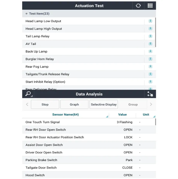
5.To forcibly actuate the input value of the module to be checked, select option 'Actuation Test'.
1.Disconnect the negative (-) battery terminal.
2.Remove the front door trim.(Refer to Body - "Front Door Trim")
3.Remove the power window switch assembly (A).
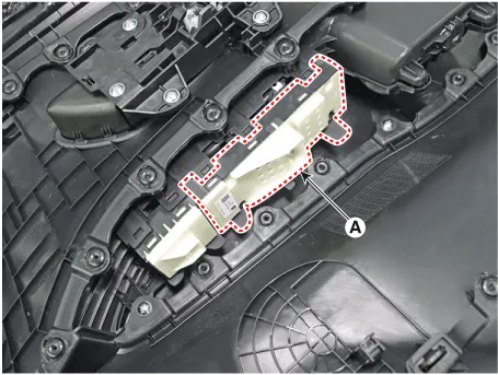
1.Install the power door lock swtich assembly.
2.Install the front door trim.
 Instrument Cluster
- Description
Cluster Variant Coding
As we have more options (SCC, VDC, EPB, Cubis, MDPS, TPMS, LDWS, ECS 등)
in the car, the dashboard now has more information to display depending
on the ch ...
Other information:
Hyundai Tucson (NX4) 2022-2026 Service Manual: Liftgate Weatherstrip
- Replacement
• Do not apply sealant to the body.
1.Remove the liftgate weatherstrip (A).
2.To install, reverse removal procedure.
• When installing the liftgate weatherstrip, check the center-marking line (B).
...
Hyundai Tucson (NX4) 2022-2026 Service Manual: Roof Rack
- Replacement
• When removing with a flat-tip screwdriver or remover, wrap protective tape around the tools to prevent damage to components.
• Put on gloves to prevent hand injuries.
1.Remove the roof trim.(Refer to Roof Trim - "Roof Trim Assembly")
2.Loosen the nu ...
