Hyundai Tucson: Front Suspension System / Front Sub Frame

• When lifting a vehicle using a lift, be careful not to damage the lower parts of the vehicle (floor under cover, fuel filter, fuel tank, canister).(Refer to General Information - "Lift and Support Points")
1.Loosen the front wheel nuts slightly.Raise the vehicle, and make sure it is securely supported.
2.Remove the front wheel and tire.(Refer to Suspension System - "Wheel")
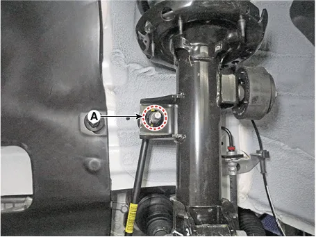
3.Remove the stabilizer link bar link from the front strut after loosening the mounting nut (A).
Tightening torque :98.1 - 117.7 N.m (10.0 - 12.0 kgf.m, 72.3 - 86.8 lb-ft)

• When loosening the nut, fix the outer hexagon of stabilizer bar link.
• Be careful not to damage the stabilizer link boots.
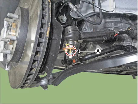
4.Loosen the tie rod end ball joint nut (A).
Tightening torque :98.0 - 117.6 N.m (10.0 - 12.0 kgf.m, 72.3 - 86.7 lb-ft)
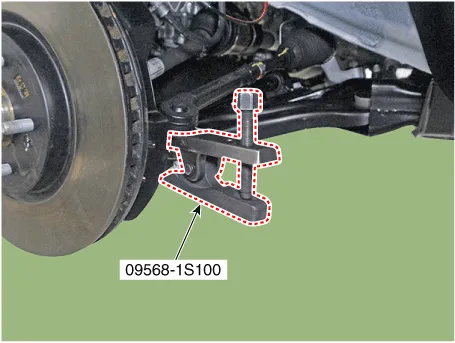
5.Remove the tie rod end ball joint using the SST (09568-1S100).
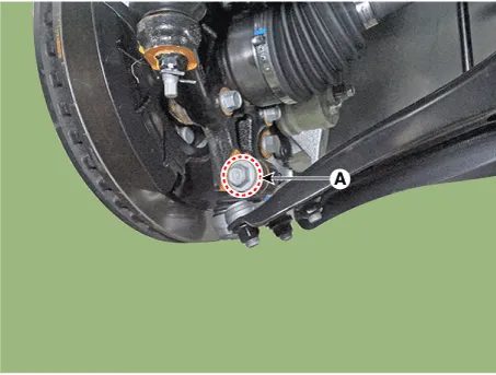
6.Loosen the front lower arm mounting bolt and nut (A).
Tightening torque :98.0 - 117.6 N.m (10.0 - 12.0 kgf.m, 72.3 - 86.7 lb-ft)
7.Remove the lower arm from the knuckle by using the SST (09568-4R100).
(1)Install the support bolt (A) from lower arm bolt hole.
(2)Install the support body (B) from front axle.
(3)Tighten the bolt (C).
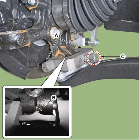
8.Separate the universal joint from the steering gear box after universal joint mounting bolt (A).
Tightening torque :53.9 - 58.8 N.m (5.5 - 6.0 kgf.m, 39.8 - 43.4 lb-ft)
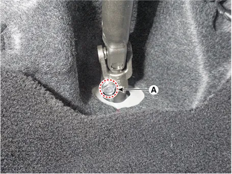

• Do not reuse the bolt.
• Lock the steering wheel in the straight ahead position to prevent the damage of the clock spring inner cable.
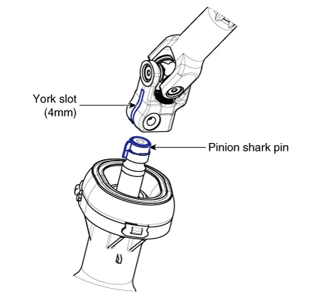
• Assemble so that the universal joint hole is inserted matching the cut surface of the pinion shaft shark pin.
9.Remove the under cover.(Refer to Engine Mechanical System - "Engine Room Under Cover")
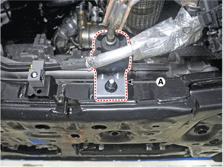
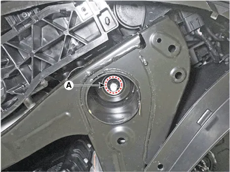
10.Remove the muffler rubber hanger (A) from the sub frame after loosening the mounting nut.
Tightening torque :19.6 - 25.5 N.m (2.0 - 2.6 kgf.m, 14.5 - 18.8 lb-ft)
11.Remove the roll rod bracket (C) after loosening the bolt (A), (B).
Tightening torque :(A) : 107.9 - 127.5 N.m (11.0 - 13.0 kgf.m, 79.6 - 94.0 lb-ft)(B) : 49.0 - 63.7 N.m (5.0 - 6.5 kgf.m, 36.2 - 47.0 lb-ft)
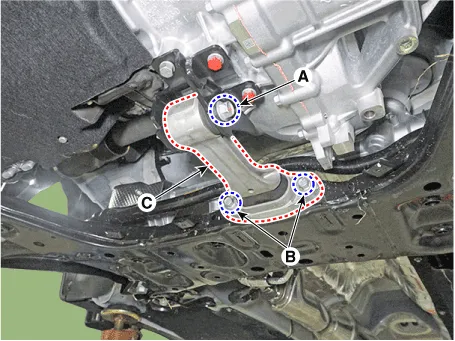

• Set a transmission jack for safety.
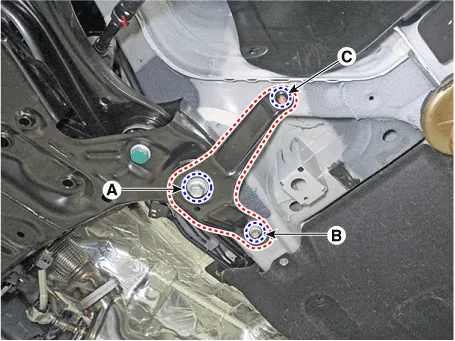
12.Remove the sub frame stay after loosening the mounting bolts (A, B) and nut (C).
Tightening torque :(A) : 176.5 - 196.1 N.m (18.0 - 20.0 kgf.m, 130.2 - 144.7 b-ft)(B) : 44.1 - 53.9 N.m (4.5 - 5.5 kgf.m, 32.5 - 39.8 lb-ft)(C) : 44.1 - 53.9 N.m (4.5 - 5.5 kgf.m, 32.5 - 39.8 lb-ft)
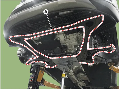
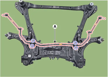
13.Loosen the sub frame mounting nuts (A).
Tightening torque :176.5 - 196.1 N.m (18.0 - 20.0 kgf.m, 130.2 - 144.7 b-ft)
14.Remove the sub frame.
15.Remove the heat protector (A).
Tightening torque :7.8 - 11.8 N.m (0.8 - 1.2 kgf.m, 5.8 - 8.7 lb-ft)
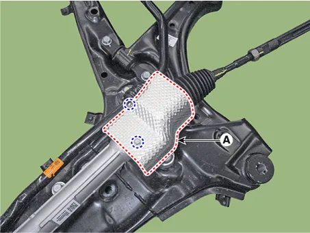
16.Remove the steering gearbox (A) from the front sub frame after loosening the mounting bolts.
Tightening torque :107.9 - 127.5 N.m (11.0 - 13.0 kgf.m, 79.6 - 94.0 lb-ft)
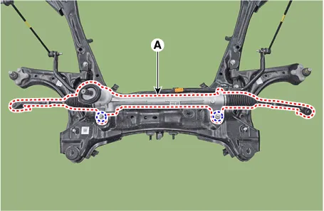
17.Remove the stabilizer bar (A) from the sub frame after loosening the mounting bolts.
Tightening torque :49.0 - 63.7 N.m (5.0 - 6.5 kgf.m, 36.2 - 47.0 lb-ft)
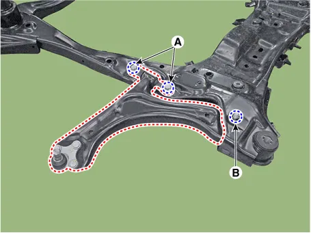
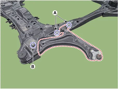
18.Remove the front lower arm after loosening the mounting bolts (A, B).
Tightening torque :(A) : 156.9 - 176.5 N.m (16.0 - 18.0 kgf.m, 115.7 - 130.2 lb-ft)(B) : 156.9 - 176.5 N.m (16.0 - 18.0 kgf.m, 115.7 - 130.2 lb-ft)
1.To install, reverse the removal procedures.
2.Check the alignment.(Refer to Suspension System - "Alingment")
 Front Stabilizer Bar
- Removal
• When lifting a vehicle using a lift, be careful not to damage
the lower parts of the vehicle (floor under cover, fuel filter, fuel
tank, canister).(Refer to Ge ...

Other information:
Hyundai Tucson (NX4) 2022-2026 Service Manual: Temperature Control Actuator
- Description
The heater unit includes mode control actuator and temperature control
actuator.The temperature control actuator is located at the heater unit.
It regulates the temperature by the procedure as follows.Signal from
control unit adjusts the position of the temperature door by ope ...
Hyundai Tucson (NX4) 2022-2026 Owner's Manual: Highway Driving Assist
Operation
Highway Driving Assist display
The status of the Highway Driving Assist
operation appears in Driving Assist mode
on the instrument cluster. Refer to the
"View Modes" section in Chapter 4.
1 Indicates if there is a vehicle ahead
and the selected distance level
appears.
Highway Driving ...
