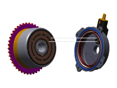
Hyundai Tucson: Engine Control System / E-CVVT Motor
| Item | Specification |
| Motor Power (Max.) | 125W / 12V (Room Temperature) |
| Control Current | Max. 48.1A (Room Temperature) |

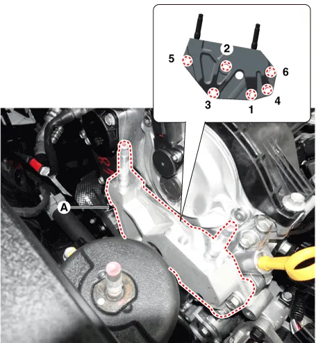
1.Remove the engine mounting bracket.(Refer to Engine Mechanical System - "Engine Mounting")
2.Remove the engine support bracket (A) after loosening the mounting bolt.

• Loosen the bolts in the sequence shown (6→5→4→3→2→1).
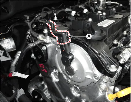
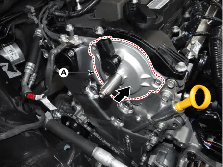
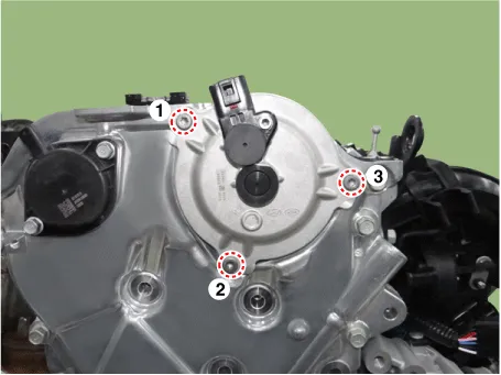
3.Remove the E-CVVT cover connector (A).
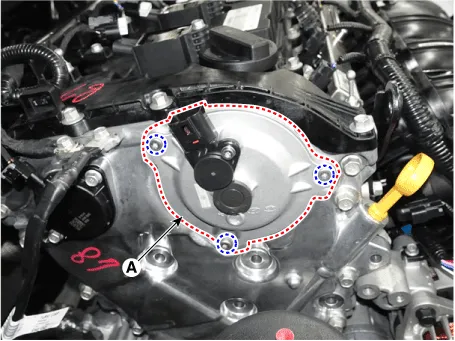
4.Remove the E-CVVT cover (A) after loosening the mounting bolt.

• Take care avoid external force to the brush after removing the cover.

• Remove after 30 minutes of switching "OFF" the ignition to drain out the oil inside the E-CVVT motor plug.
1.Remove the timing chain.(Refer to Engine Mechanical System - "Timing Chain")
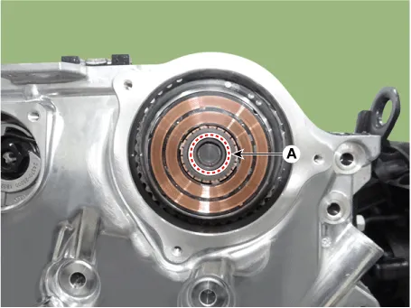
2.Remove the center of the E-CVVT motor plug (A) by breakig it.

• Do not tilt the front of engine (timing chain cover side) downward as residual oil may flow out during E-CVVT motor plug removal.
• If oil flows out during E-CVVT motor plug removal, wipe off immediately and block the motor shaft inlet with a clean towel.
3.Fix the camshaft part (A) using the wrench, and then remove the E-CVVT motor (B) after loosening the mounting bolt.

1.Remove the center of the E-CVVT motor plug (A) by breakig it.


• Remove after 30 minutes of switching "OFF" the ignition to drain out the oil inside the E-CVVT motor plug.
• Do not tilt the front of engine (timing chain cover side) downward as residual oil may flow out during E-CVVT motor plug removal.
• If oil flows out during E-CVVT motor plug removal, wipe off immediately and block the motor shaft inlet with a clean towel.
2.Clean the E-CVVT motor plug mounting surface (A) with oil cleaner.

• If the surface is not cleaned, E-CVVT motor plug may be separated due to diminished separation force from residual oil.
• When spraying oil cleaner, block around the motor shaft inlet and rotor gap with a clean towel to prevent inflow of oil from flowing into the rotor gap.
3.When reusing the E-CVVT cover, inspect the below items.
(1)If there is sign of leakage from inside the E-CVVT cover, replace it with a new one.
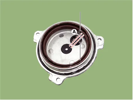
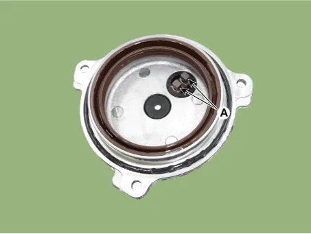
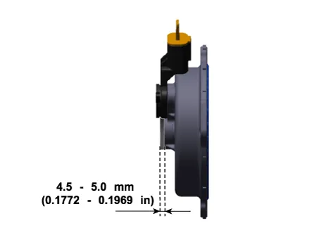
(2)Check for worn connector brush (A).
Specification : Over 5 mm (0.1969 in.)
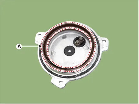
(3)Check for damaged oil seal (A) and replace any damaged E-CVVT cover with a new one.
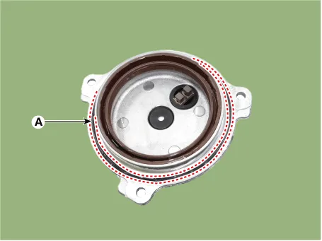
(4)After inspecting E-CVVT, if no problem is found, replace the o-ring (A) with a new one.
4.Install the E-CVVT cover.
(1)Apply engine oil on oil seal lip (A).
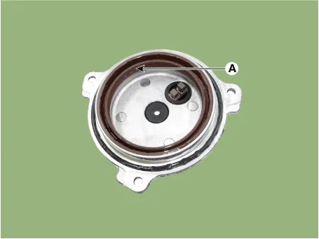

• When applying oil, keep the connector brush (A) clean from foreign materials.
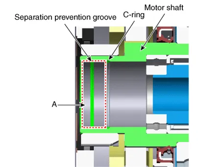
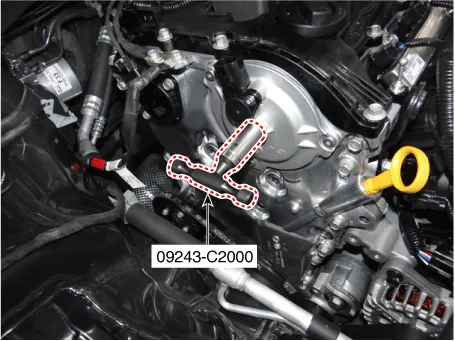
(2)Insert SST (09243-C2000) into the E-CVVT motor shaft.
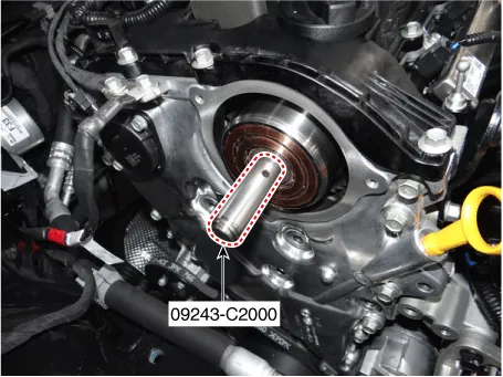

• Correctly mount SST onto the motor shaft.
(3)Slowly push the E-CVVT cover (A) until it is flush with the timing chain cover surface.

• Installing the E-CVVT cover without SST may cause oil leakage inside the E-CVVT motor due to damaged or separated E-CVVT oil seal.
(4)Pre-tighten the bolts in the below sequence, and then remove the SST (09243-C2000).
Tightening torque :1.0 - 2.0 N.m (0.1 - 0.2 kgf.m, 0.7 - 1.4 lb-ft)
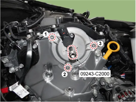
(5)Tighten the bolts to the specified torque in the sequence below.
Tightening torque :9.8 - 11.8 N.m (1.0 - 1.2 kgf.m, 7.2 - 8.7 lb-ft)
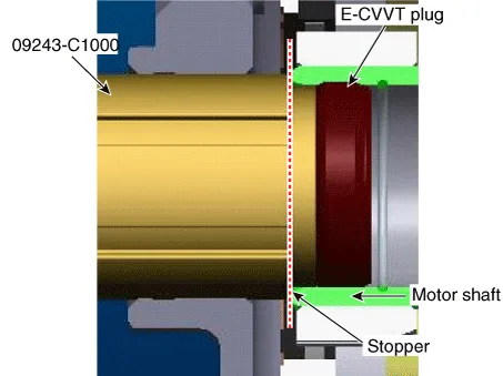
5.Install the E-CVVT plug.
(1)By using SST (09243-C2000), insert the plug into the E-CVVT cover hole.
(2)Mount the stopper of SST so that it sits at the end of E-CVVT motor shaft.
6.Inspect the pressed depth of E-CVVT plug.
(1)By using a steel ruler, measure the distance from E-CVVT cover center boss to the end of motor shaft (â‘ ).
(2)By using a steel ruler, measure the distance from E-CVVT cover center boss to the end of E-CVVT plug (②).
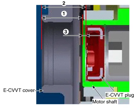
(3)Calculate the pressed depth (③) of motor plug.If out of specification, reinstall after replacing the E-CVVT plug with a new one.
Pressed depth : ③ = ② - ①Specification : 1.1 - 2.1 mm (0.0433 - 0.0827 in.)
7.Insert the E-CVVT cover plug so that the protrusion reach to E-CVVT cover groove correctly.
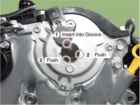

• Check how much protrude after installing the E-CVVT plug.
• Be careful that the plug is not inserted inside E-CVVT cover beyond the regulated range.
8.Install the engine support bracket (A).
Tightening torque :39.2 - 44.1 N.m (4.0 - 4.5 kgf.m, 28.9 - 32.5 lb-ft)
(1)Pre-tighten the bolts in the sequence (1→2→3).
(2)Turn the bracket counterclockwise and then tightening the bolt 1.
(3)And then tighten the bolt in the sequence (2→3→4→5→6).

9.Install the engine mounting bracket.(Refer to Engine Mechanical System - "Engine Mounting")
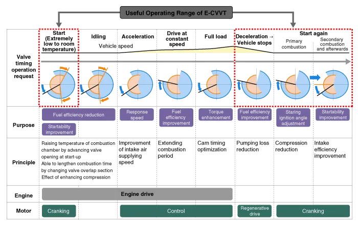
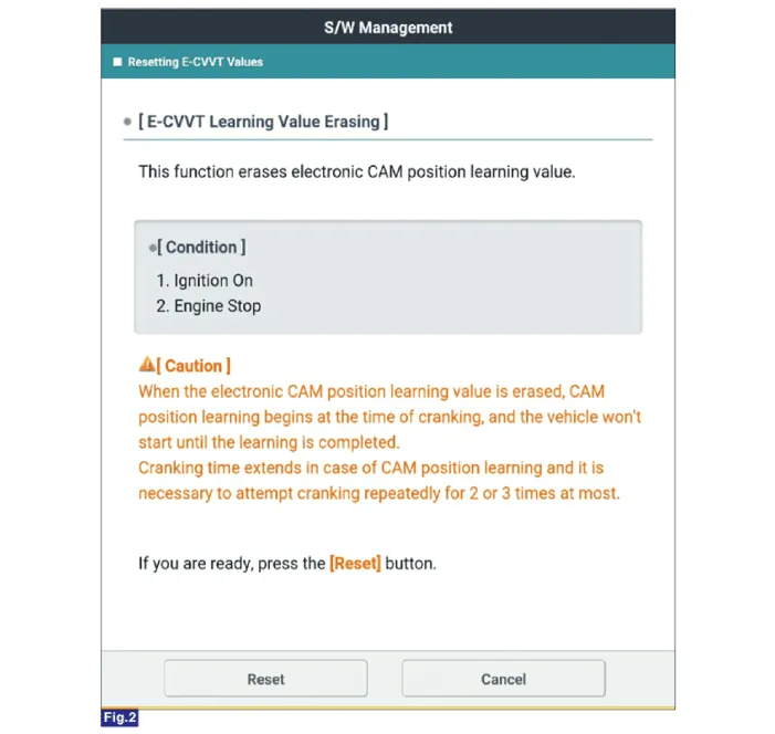
10.Perform the E-CVVT learning value erasing using the diagnosis tool.

• After replacing or remounting the E-CVVT assembly, be sure to reset the learned value from the additional feature menu on the diagnostic device.
• When the learned value for electronic cam position is erased, start learning the cam position while cranking. The engine can start once this is completed.
• Cranking should be repeated for up to 2-3 times to complete learning.

1.Install the E-CVVT motor (A).
Tightening torque :73.5 - 83.4 N.m (7.5 - 8.5 kgf.m, 54.2 - 61.5 lb-ft)
2.Fix the camshaft part (A) using the wrench, and then remove the E-CVVT motor (B) after loosening the mounting bolt.
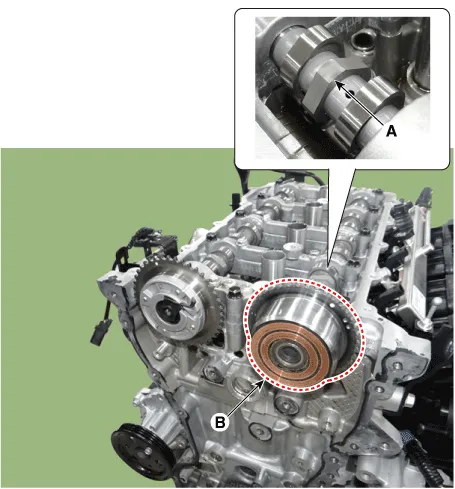

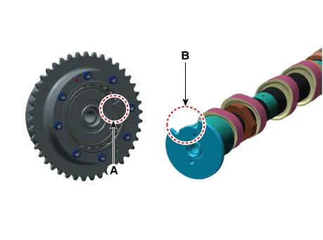
• Tighten the bolts with the E-CVVT stopper (A) and the camshaft slot (B) in contact.
3.Install the timing chain.(Refer to Engine Mechanical System - "Timing Chain")
4.Perform the E-CVVT learning value erasing using the diagnosis tool.

• After replacing or remounting the E-CVVT assembly, be sure to reset the learned value from the additional feature menu on the diagnostic device.
• When the learned value for electronic cam position is erased, start learning the cam position while cranking. The engine can start once this is completed.
• Cranking should be repeated for up to 2-3 times to complete learning.
 Variable Intake Solenoid (VIS) Valve
- Description
Variable Intake manifold Solenoid (VIS) valve is installed on the
intake manifold. The VIS valve controls the vacuum modulator which
activates a valve in the intake manifold. The ...
 Canister Close Valve (CCV)
- Description
Canister Close Valve (CCV) is normally open and is installed on the
canister ventilation line. It seals evaporative emission control system
by shutting the canister from the atmos ...
Other information:
Hyundai Tucson (NX4) 2022-2026 Owner's Manual: Pretensioner seat belt (for driver
and front passenger seat)
1: Retractor pretensioner,
2: Emergency fastening device (for driver’s seat only)
Your vehicle is equipped with driver’s
Pretensioner seat belts (Retractor
Pretensioner and Emergency Fastening
Device System). The pretensioner makes
sure the driver's and front passenger's
seat belt ...
Hyundai Tucson (NX4) 2022-2026 Owner's Manual: Smart Cruise Control (SCC)
Basic function
Smart Cruise Control uses the front view
camera and front radar to help detect a
vehicle ahead and maintain the desired
speed and distance between your vehicle
and the vehicle ahead.
Overtake Assist Control
While Smart Cruise Control is operating,
if the function judges y ...
