Hyundai Tucson: AVN System / AVN Head Unit
| No | Connector A (ExternalAmplifier) | Connector A (Internal Amplifier) | Connector B | Connector C |
| 1 | - | Rear door speaker LH (+) | Mic2 (+) | - |
| 2 | - | Rear door speaker LH (-) | Mic1 (+) | I -CAN (High) |
| 3 | Navigation voice (+) | - | - | - |
| 4 | External amplifier SPDIF (+) | - | - | - |
| 5 | Reset | Reset | - | - |
| 6 | Camera power | Camera power | Illumination (+) | - |
| 7 | Camera video | Camera video | M-CAN (High) | - |
| 8 | - | - | - | - |
| 9 | - | - | - | I -CAN (Low) |
| 10 | - | - | Battery (+) | - |
| 11 | DETECT | DETECT | Battery (+) | - |
| 12 | Steering wheel remote | Steering wheel remote | Ground | - |
| 13 | - | Front door speaker LH (+) | Ground | - |
| 14 | - | Front door speaker LH (-) | Mic2 (-) | - |
| 15 | - | Front door speaker RH (-) | Mic1 (-) | - |
| 16 | - | Front door speaker RH (+) | - | MTS |
| 17 | Navigation voice (-) | - | - | - |
| 18 | External amplifier SPDIF (-) | - | - | - |
| 19 | External amplifier SPDIF (Ground) | - | Illumination (-) | - |
| 20 | Camera power ground | Camera power ground | M-CAN (Low) | - |
| 21 | Camera video ground | Camera video ground | - | - |
| 22 | - | - | ACC | |
| 23 | - | - | Keyboard power | |
| 24 | - | - | Front monitor power | |
| 25 | - | - | - | |
| 26 | Steering wheel remote ground | Steering wheel remote ground | - | |
| 27 | - | Rear door speaker RH (-) | - | |
| 28 | - | Rear door speaker RH (+) | - | |
| 29 | - | - | - | |
| 30 | - | - | - | |
| 31 | - | - | - | |
| 32 | Camera Detect (RVM : - / SVM : Ground) | Camera Detect (RVM : - / SVM : Ground) | - | |
| 33 | Camera shield ground | Camera video shield | IGN 1 | |
| 34 | - | - | Keyboard ground | |
| 35 | - | - | Front motor ground | |
| 36 | - | - | ||
| 37 | - | - | ||
| 38 | Vehicle speed | Vehicle speed |
1.Disconnect the negative (-) battery terminal.
2.Remove the front monitor lower cover (A).
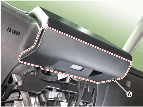
3.Remove the front monitor lower cover after disconnecting the mood lamp connector (A).
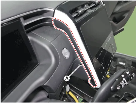
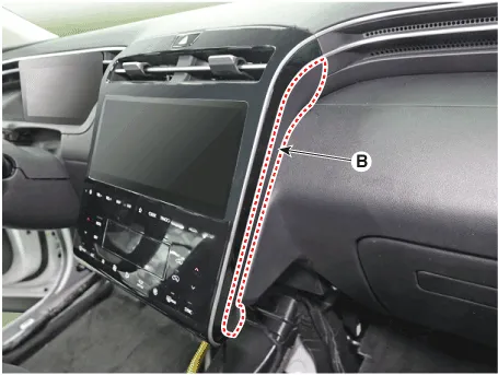
4.Remove front monitor side cover (A) and (B).
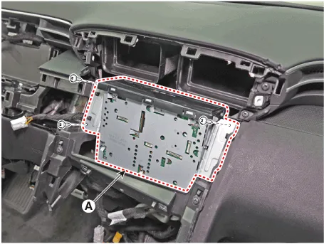
5.Remove the front monitor assembly (A).
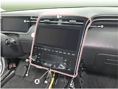
6.Remove the front monitor assembly (A) after disconnecting monitor connectors.
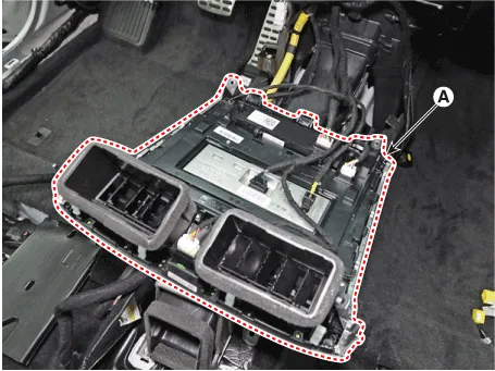
7.Remove the AVN head unit after loosening mounting screws.
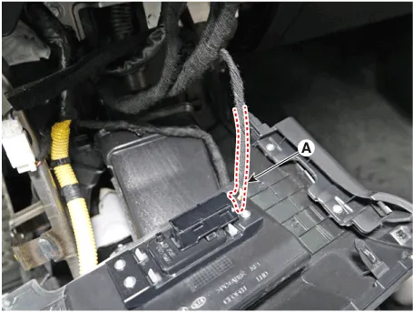
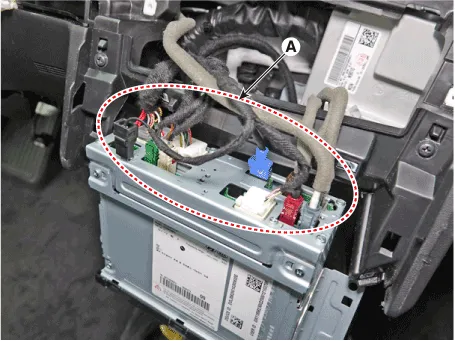
8.Remove the AVN head unit after disconnect audio connectors (A).
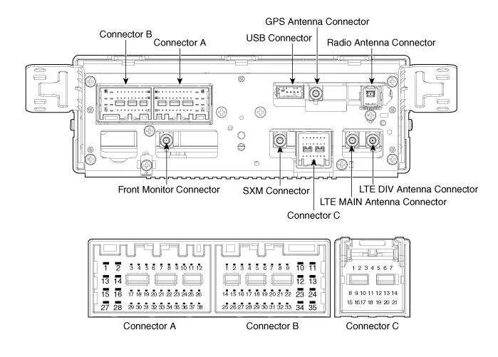
1.Install AVN head unit connectors and antenna connectors.
2.Install the AVN head unit.
3.Install the front monitor assembly.
4.Install the front monitor side cover.
5.Install the front monitor lower cover.
6.Connect the negative (-) battery terminal.

• Make sure the connector are connected in properly.
• Check the AVN system for normal operation. (navigation, radio, USB, bluetooth)
 Specifications
- Specifications
ItemSpecification
Power sourceDC 14.4V (-) ground
Frequency range / Channel spaceFM : 87.5 - 108.0 MHz / 100 KHzAM : 531 - 1602 KHz / 9 KHz
Tuning typePLL SYNTHESIZED TUNING
Im ...
 External Amplifier
- Components
Connector Pin Information
NoConnector AConnector B
1Battery (+)Front right door tweeter speaker (+)
2Battery (+)Front left door tweeter speaker (+)
3Battery (+)Sub woofer speake ...
Other information:
Hyundai Tucson (NX4) 2022-2026 Service Manual: Brake Pedal
- Components
1. Brake member assembly2. Stop lamp switch3. Brake pedal arm assembly4. Brake pedal pad
- Removal
1.Turn ignition switch OFF and disconnect the negative (-) battery cable.
2.Remove the crash pad lower panel.(Refer to Body - "Crash Pad Lower Panel")
3.Disconnect the sto ...
Hyundai Tucson (NX4) 2022-2026 Service Manual: Seat Heater (Air Ventilation)
- Components
1. Seat cushion heater (Ventilation)2. Seat heater (Ventilation) unit 3. Seat back heater(Ventilation)
- Circuit Diagram
PinConnector AConnector B
1IGN 1Ventilation heater battery (+)
2Blower power_LHHeater power_LH
3Blower speed_LHHeater power_RH
4Blower RPM input_L ...
