Hyundai Tucson: SRSCM / SRS Control Module (SRSCM)
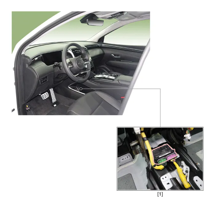
1. Supplemental Restraint System Control Module (SRSCM)
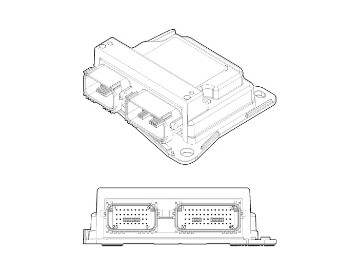
| No | Connector A | Connector B |
| 1 | Driver airbag #2 (High) | Rear driver seat belt pretensioner (High) |
| 2 | Driver airbag #2 (Low) | - |
| 3 | Passenger airbag #2 (Low) | - |
| 4 | Passenger airbag #2 (High) | - |
| 5 | Passenger airbag #3 (High) | - |
| 6 | Passenger airbag #3 (Low) | - |
| 7 | Passenger airbag active vent (Low) | - |
| 8 | Passenger airbag active vent (High) | Driver curtain airbag (High) |
| 9 | Driver airbag tether (High) | Driver curtain airbag (Low) |
| 10 | B+ | Passenger curtain airbag (High) |
| 11 | Crash output | Passenger curtain airbag (Low) |
| 12 | Passenger airbag #1 (Low) | - |
| 13 | Passenger airbag #1 (High) | - |
| 14 | - | Rear driver seat belt pretensioner (Low) |
| 15 | - | - |
| 16 | Passenger airbag OFF Lamp (Telltale) | - |
| 17 | Passenger airbag on lamp | Front center side airbag (Low) |
| 18 | - | Front center side airbag (High) |
| 19 | Driver airbag #1 (High) | - |
| 20 | Driver airbag #1 (Low) | - |
| 21 | - | Front passenger side airbag (Low) |
| 22 | - | Front passenger side airbag (High) |
| 23 | - | Front driver side airbag (High) |
| 24 | - | Front driver side airbag (Low) |
| 25 | - | - |
| 26 | C-CAN (Low) | - |
| 27 | C-CAN (High) | Front driver retractor pretensioner (Low) |
| 28 | IGN 1 | Front driver retractor pretensioner (High) |
| 29 | Driver front impact sensor (High) | - |
| 30 | Driver front impact sensor (Low) | - |
| 31 | Passenger front impact sensor (Low) | - |
| 32 | Passenger front impact sensor (High) | Front passenger retractor pretensioner (High) |
| 33 | Passenger airbag on / off switch (High) | Front passenger retractor pretensioner (Low) |
| 34 | Passenger airbag on / off switch (Low) | - |
| 35 | - | - |
| 36 | - | - |
| 37 | - | - |
| 38 | Rear passenger retractor pretensioner (Low) | |
| 39 | Rear passenger retractor pretensioner (High) | |
| 40 | Ground | |
| 41 | Rear driver impact sensor (Low) | |
| 42 | Rear driver impact sensor (High) | |
| 43 | Driver pressure side impact sensor (High) | |
| 44 | Driver pressure side impact sensor (Low) | |
| 45 | Passenger pressure side impact sensor (Low) | |
| 46 | Passenger pressure side impact sensor (High) | |
| 47 | Front driver side impact sensor (High) | |
| 48 | Front driver side impact sensor (Low) | |
| 49 | Front passenger side impact sensor (Low) | |
| 50 | Front passenger side impact sensor (High) | |
| 51 | Rear passenger side impact sensor (High) | |
| 52 | Rear passenger side impact sensor (Low) |
1.Disconnect the battery negative terminal.

• After disconnecting the cables, wait at least 3 minutes.
2.Remove the floor console assembly.(Refer to Body - "Floor Console Assembly")
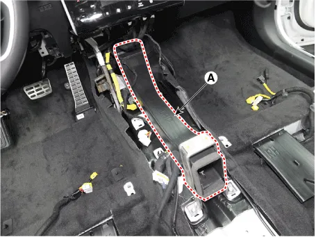
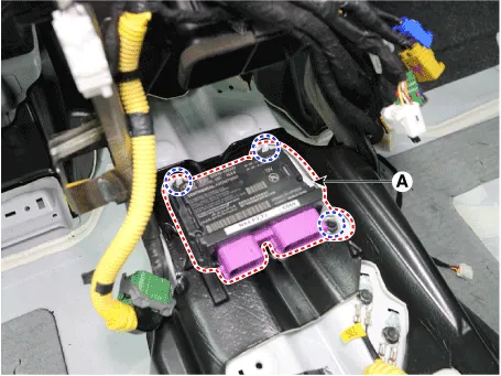
3.Remove the rear air duct (A) by removing the mounting bolt.
4.Pull up the lock of the SRSCM connector to disconnect the connectors (A).
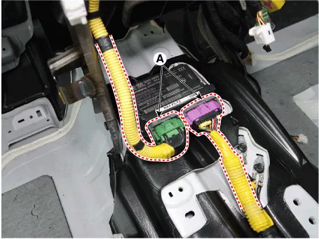
5.Remove the SRSCM mounting bolt and nuts, remove the SRSCM (A).
Tightening torque :Bolt : 10.8 - 13.7 N.m (1.1 - 1.4 kgf.m, 7.9 - 10.1 lb-ft)Nut : 7.8 - 9.8 N.m (0.8 - 1.0 kgf.m, 5.8 - 7.2 lb-ft)
1.Install in the reverse of the removal.
2.After installing the SRSCM, confirm proper system operation.

• SIf the Switch ON the ignition, the SRS indicator light should turn on for about six seconds and then off.
1.Connect the cable of self-diagnosis to the data link connector in driver side crash pad lower panel, and turn on the self-diagnosis.
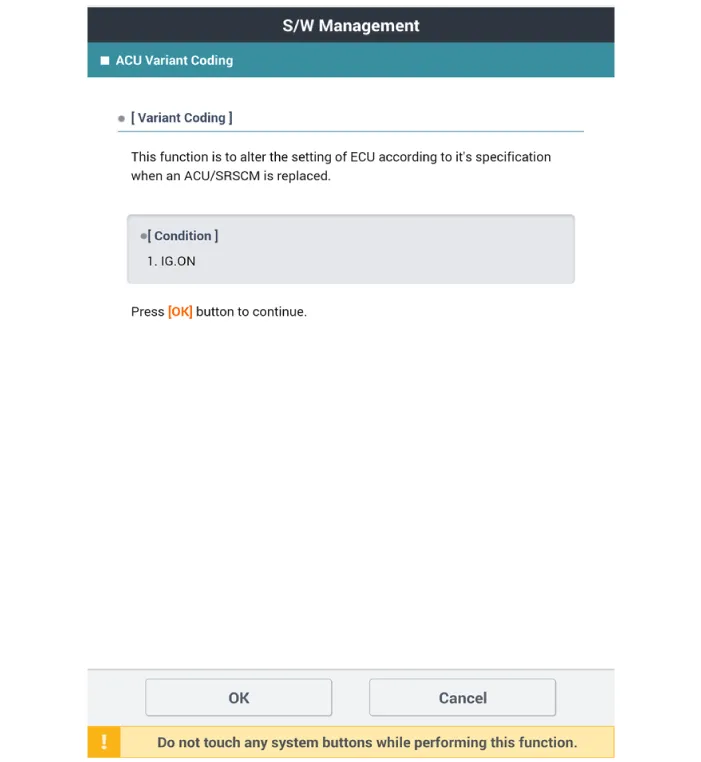
2.Select "Airbag" and "ACU Variant Coding".
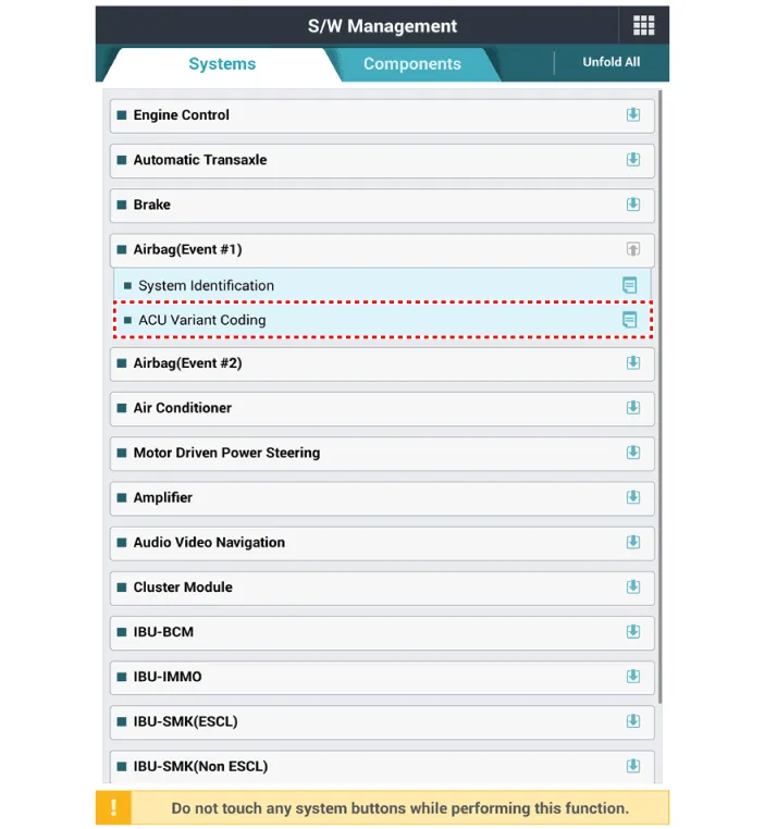
3.Perform the "ACU/SRSCM Variant Coding" procedure according to the self-diagnosis screen message.
 Components and Components Location
- Components Location
1. Supplemental Restraint System Control Module (SRSCM)2. Gravity Side Impact Sensor (G-SIS) _ C pillar3. Gravity Side Impact Sensor (G-SIS) _ B pillar4. Front Impact Sens ...
 Front Impact Sensor (FIS)
- Description
• The front impact sensors (FIS) are installed on the upper of the
side panel in Front End Module (FEM). They are remote sensors that
detect acceleration due to a collision at ...
Other information:
Hyundai Tucson (NX4) 2022-2026 Service Manual: Auto Defoging Actuator
- Description
The auto defogging sensor is installed on the front window glass. The
sensor judges and sends signal if moisture occurs to blow out wind for
defogging. The air conditioner control module receives a signal from the
sensor and restrains moisture and eliminates defog by the intak ...
Hyundai Tucson (NX4) 2022-2026 Service Manual: Heater Unit
- Component Location
1. Heater unit assembly
- Components
1. Heater unit assembly2. Heater core cover3. Heater core assembly4. Mode control actuator [LH]5. DEF duct seal6. Evaporator assembly7. Flange seal8. Heater NVH pad9. Temperature control actuator [LH]10. Heater case [LH]11. Ve ...
