Hyundai Tucson: Air Conditioning System / Refrigerant Line
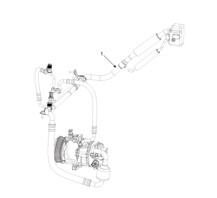
1. Suction & Liquid Pipe Assembly
1.If a compressor is available, the air conditioner is operated for a few minutes in the engine idle state and then the engine is stopped.
2.Disconnect the negative (-) battery terminal.
3.Recover the refrigerant with a recovery/charging station.(Refer to Air conditioning System - "Repair procedures")
4.Remove the engine cover.(Refer to Engine Mechanical System - "Engine Cover")
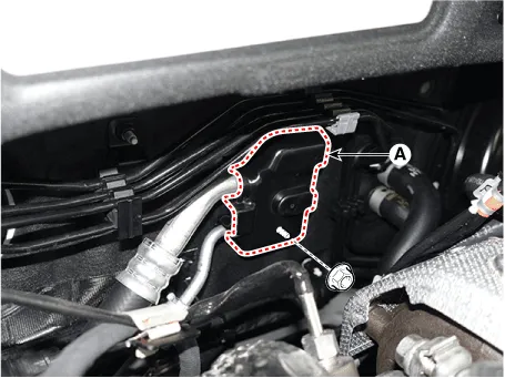
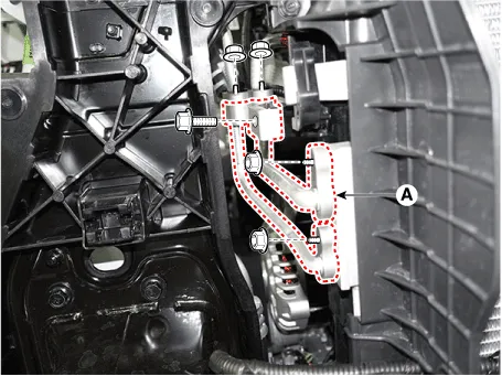
5.Loosen the mounting nut and separate the expansion valve cover (A).
Tightening torque : 7.8 - 11.8 N.m (0.8 - 1.2 kgf.m, 5.8 - 8.7 lb-ft)
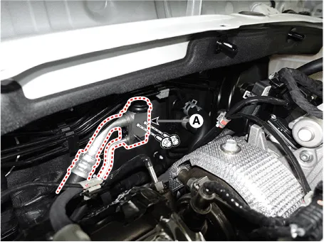
6.Loosen the mounting bolts and separate the expansion valve (A) fron evaporator core.
Tightening torque : 21.6 - 32.4 N.m (2.2 - 3.3 kgf.m, 15.9 - 23.9 lb-ft)
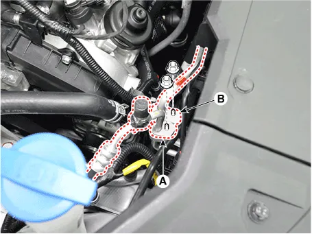
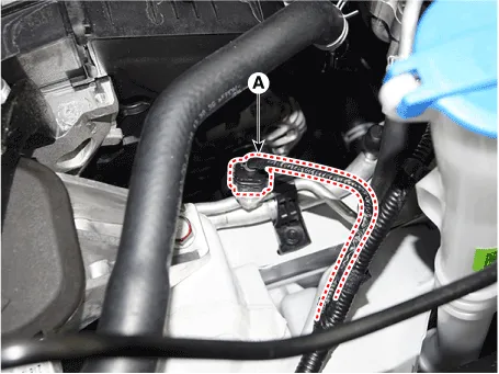
7.Loosen the mounting nuts and separate the suction line (A), discharge line (B).
Tightening torque : 19.6 - 23.5 N.m (2.0 - 2.4 kgf.m, 14.5 - 17.4 lb-ft)
8.Disconnect the APT sensor connector (A).
9.Remove the engine room under cover.(Refer to Engine Mechanical System - "Engine Room Under Cover")
10.Remove the engine mounting braket.(Refer to Engine Mechanical System - "Engine Mounting")
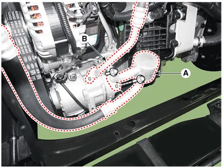
11.Separate the compressor suction line (A) and discharge line (B) connection nuts and disconnect the line.
Tightening torque : 21.6 - 32.4 N.m (2.2 - 3.3 kgf.m, 15.9 - 23.9 lb-ft)

• Be careful not to damage the parts located under the vehicle (floor under cover, fuel filter, fuel tank and canister) when raising the vehicle using the lift.(Refer to General Information - "Lift and Support Points")
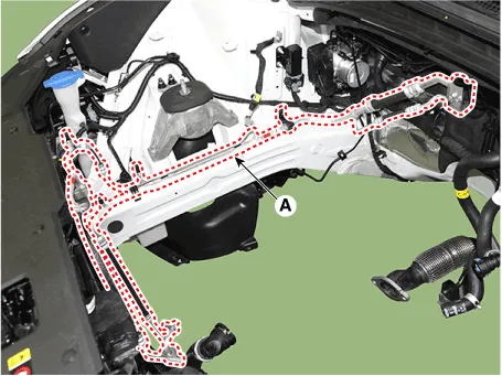
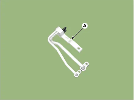
12.Loosen the mounting bolt and remove the Front suction & Liquid pipe assembly (A).
Tightening torque : 7.8 - 11.8 N.m (0.8 - 1.2 kgf.m, 5.8 - 8.7 lb-ft)
13.Install in the reverse order of removal.

• Plug or cap the lines immediately after disconnecting them to avoid moisture and dust contamination.
• Tighten the bolt or nut joint to the specified torque.
• Using a gas leak detector, check for refrigerant leakage.
• Evacuate air in the refrigeration system and charge system with refrigerant.
Capacity : R-1234yf : 550 ± 25g (17.7 ± 0.88oz)R-134a : 550 ± 25g (17.68 ± 0.88oz)
1.Remove the front bumper assembly.(Refer to Body (Interior and Exterior) - "Front Bumper Assembly")
2.Recover the refrigerant with a recovery/charging station.(Refer to Air conditioning System - "Repair procedures")
3.Loosen the mounting nuts, and then disconnect the liquid line (A) from the condenser.
Tightening torque : 7.8 - 11.8 N.m (0.8 - 1.2 kgf.m, 5.8 - 8.7 lb-ft)
4.Install in the reverse order of removal.

• Plug or cap the lines immediately after disconnecting them to avoid moisture and dust contamination.
• Tighten the bolt or nut joint to the specified torque.
• Using a gas leak detector, check for refrigerant leakage.
• Evacuate air in the refrigeration system and charge system with refrigerant.
Capacity : R-1234yf : 550 ± 25g (17.7 ± 0.88oz)R-134a : 550 ± 25g (17.68 ± 0.88oz)
 Compressor oil
- Oil Specification
1.The R-134a or R-1234yf system requires synthetic (PAG) compressor
oil whereas the R-12 system requires mineral compressor oil. The two
oils must never be mixed.
2.Compre ...
 Compressor
- Description
The compressor is the power unit of the A/C system.It is located on the
side of engine block and driven by a V-belt of the engine.The
compressor changes low pressure and low tempe ...
Other information:
Hyundai Tucson (NX4) 2022-2026 Owner's Manual: Motor Driven Power Steering
(MDPS) warning light. Charging system warning
light
Motor Driven Power Steering
(MDPS) warning light
This warning light illuminates:
When the ignition switch is in the ON
position. The Motor Driven Power
Steering warning light illuminates for
about 3 seconds and then goes off.
Whenever there is a malfunction with
the motor driv ...
Hyundai Tucson (NX4) 2022-2026 Owner's Manual: Before Driving
Before Entering the Vehicle
Make sure all windows, outside
mirror(s), and outside lights are clean
and unobstructed.
Remove frost, snow, or ice from both
the front and rear windshield as well
as the front side windows.
Visually check the tires for uneven
wear and damage.
Che ...
