Hyundai Tucson: Automatic Transaxle Control System / Position Sensor
| Item | Specification |
| Output type | Non-Contact type (2 channels, PWM signal output) |
| Input power (V) | 4.5 - 5.5 |
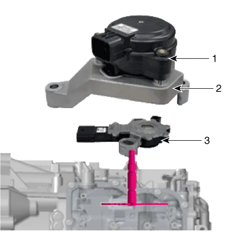
1. Electric shift actuator
2. Bracket
3.Position sensor
| Major Symptom | Expected Cause | Items to Check and Measures |
| Shock when shifting to and from D/R Motor run-up when shifting to and from D/R | Faulty position sensor "N" setting | Use the "N" setting jig and adjust the "N" setting. |
| (Refer to "Automatic Transaxle System – Position Sensor") | ||
| Faulty oil pressure in the valve body | Replace valve body assembly or inspect/replace transaxle assembly | |
| Faulty engine start Current gear not indicated in the Cluster Warning Lamp ON Engine stall while stopped Creeping not possible Auto parking release disabled | Faulty CAN terminating resistance/circuit | Check TCM/battery management system module. |
| Check TCM wiring connector connection. | ||
| Faulty position sensor circuit fuse | Check fuse and junction box terminal, and repair. | |
| Faulty position sensor wiring connector | Check for foreign substance in the wiring connector, and check for gap on the terminal. | |
| Check sealing on unused pin, and check for corrosion on the terminal. | ||
| Faulty reverse lamp circuit | Check reverse lamp ground, and reassemble if necessary. | |
| Faulty position sensor wiring ground | Check wiring ground, and reassemble if necessary. | |
| Position sensor faulty code | Inspect in accordance with the inspection flow, then replace position sensor if necessary. |

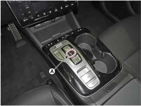
• With the ignition off, press the brake pedal and press the "N" button (A) for 3 seconds.
1.Turn ignition switch OFF and disconnect the negative (-) battery cable.
2.Remove the air cleaner assembly and air duct.(Refer to Engine Mechanical System - "Air cleaner")
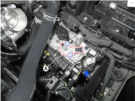
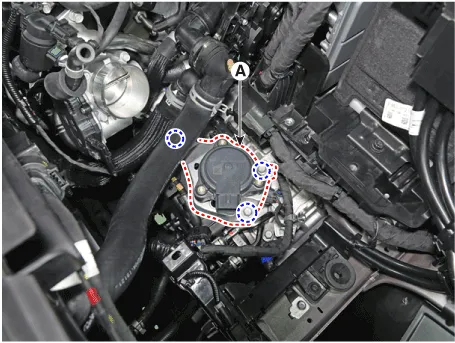
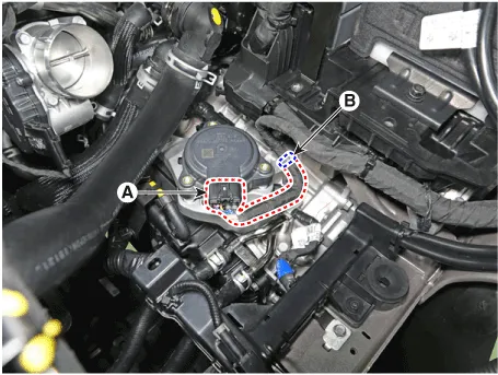
3.Disconnect the electronic shift actuator connector (A) and then separate the wiring clip (B).

4.Loosen the bolts and then removing the electronic shift actuator (A).

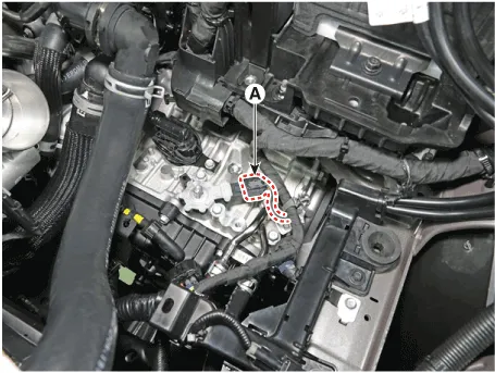
5.Disconnect the position sensor connector (A).

6.Loosen the bolts and then removing the position sensor (A).
1.Check that the shaft (A) is in the "N" position.
2.Install the position sensor (B).
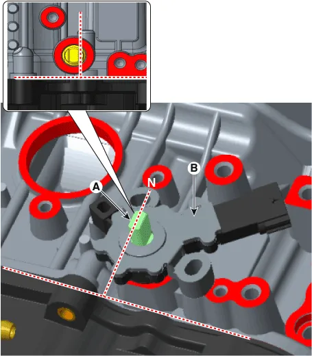
3.Install the position sensor "N" fixing SST(No.:09459 - 4G100)(D) in the sensor (A), case pin (B) and anti-rotation guide (C).
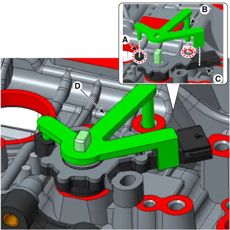
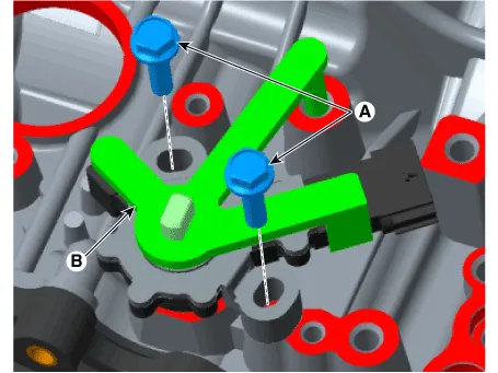
4.Tighten the bolts (A) in the position sensor and then removing the "N" fixing SST(No.:09459 - 4G100)(B).
Tightening torque :9.8 - 11.8 N.m (1.0 - 1.2 kgf.m, 7.2 - 8.7 lb-ft)
5.Connect the position sensor connector (A).
6.Install the electronic shift actuator (A).
Tightening torque :20.6 - 26.5 N.m (2.1 - 2.7 kgf.m, 15.2 - 19.5 lb-ft)
7.Connect the electronic shift actuator connector (A) and wiring clip (B).
8.Install the air duct and the air cleaner assembly.(Refer to Engine Mechanical System - "Air cleaner")
9.Check that operating surely at each range of the position sensor corresponding to each position of electric shift button.
 Speed Sensor
- Description
Input speed sensor : Used for detecting the speed of OD drumOutput
speed sensor : Used for detecting the speed of transfer drive gearMiddle
speed sensor : Used as a signal for red ...
 Electric Shift Button
- Removal
1.Turn ignition switch OFF and disconnect the negative (-) battery cable.
2.Remove the console upper cover.(Refer to Body (Interior and Exterior) - "Floor Console Assembly")
3.Loosen ...
Other information:
Hyundai Tucson (NX4) 2022-2026 Owner's Manual: Tire Replacement
If the tire is worn evenly, a tread
wear indicator appears as a solid
band across the tread. This shows
there is less than 1/16 inch (1.6mm) of
tread left on the tire. Replace the tire
when this happens.
Do not wait for the band to appear
across the entire tread before
replacing the ...
Hyundai Tucson (NX4) 2022-2026 Service Manual: Rear Door Side Weatherstrip
- Replacement
[Rear door side weatherstrip]
1.Loosen the rear door checker (B) mounting bolt.Tightening torque :16.7 - 21.6 N.m (1.7 - 2.2 kgf.m, 12.3 - 15.9 lb-ft)
2.Detach the clips, then remove the rear door side weatherstrip (A).
3.To install, reverse removal procedure.
[Rear door bod ...
