Hyundai Tucson: Power Liftgate Module / Inspection

• FOB key Switch : FOB key Switch → BMC / SMK → CAN communication → PTG Module
• Driver Switch : Driver Switch → Wiring → PTG Module
• Outer Switch : Outer Switch → Wiring → SJB → CAN communication → PTG Module
①Press the power liftgate open switch② Transmit / receive power liftgate open signal via CAN communication and wiring ③ Power liftgate open

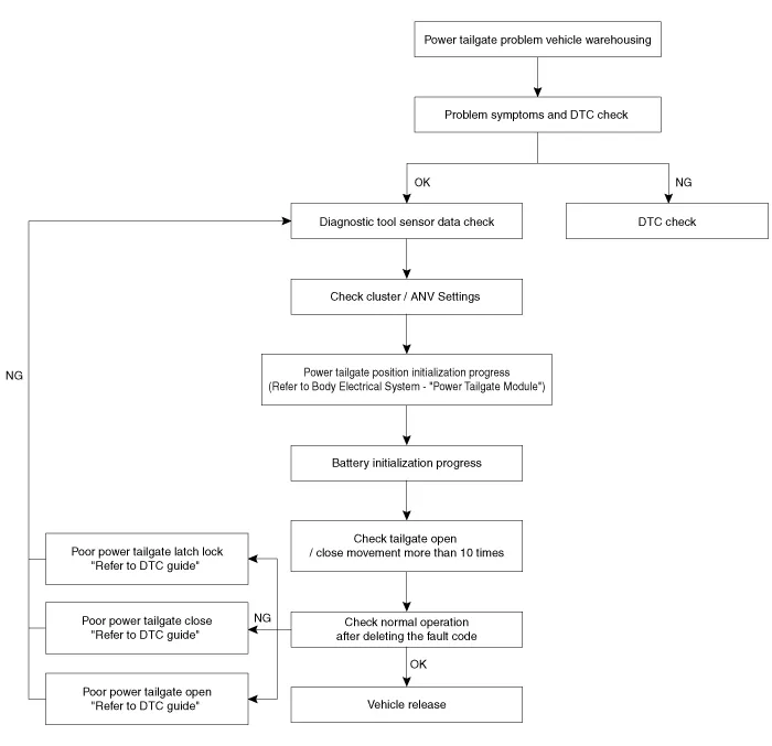
• The operation of the power liftgate is activated by mutual communication with the vehicle's module and switch.
• Before replacing parts, it is necessary to check the basic communication, switch signals, and contact points of wire connectors.
| List | Solution |
| CAN BUS OFF | Check CAN Line |
| Power Liftgate Module Inline Mode Not Deactivated | 1. S/W Management - Disable Inline Mode |
| 2. Disable inline mode by driving (5 km/h↑) | |
| PTG Unlatch Error | 1. Check latch connector plugged in properly |
| 2. Check latch wiring | |
| 3. Check latch assembly | |
| PTG Spindle Hall Sensor Error, LH | 1. Check spindle connector plugged in properly - LH |
| 2. Check spindle wiring - LH | |
| 3. Check spindle assembly - LH | |
| PTG Spindle Hall Sensor Error, RH | 1. Check spindle connector plugged in properly - RH |
| 2. Check spindle wiring - RH | |
| 3. Check spindle assembly - RH | |
| PTG Anti-Pinch Sensor Error, LH | 1. Check anti-pinch sensor connector plugged in properly - LH |
| 2. Check anti-pinch sensor wiring - LH | |
| 3. Check anti-pinch sensor assembly - LH | |
| PTG Anti-Pinch Sensor Error, RH | 1. Check anti-pinch sensor connector plugged in properly - RH |
| 2. Check anti-pinch sensor wiring - RH | |
| 3. Check anti-pinch sensor assembly - RH | |
| PTG Latch Cinching Rewinding Fail Max | 1. Check latch connector plugged in properly |
| 2. Check latch wiring | |
| 3. Check latch assembly | |
| PTG Integrated Latch Home Position Switch Error | 1. Check latch connector plugged in properly |
| 2. Check latch wiring | |
| 3. Check latch internal switch signal | |
| 4. Check latch assembly | |
| PTG Integrated Latch Switch Combination Error | 1. Check latch connector plugged in properly |
| 2. Check latch wiring | |
| 3. Check latch internal switch signal | |
| 4. Check latch assembly |
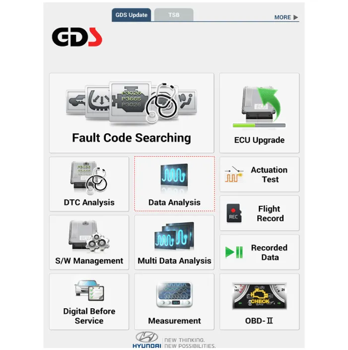
1.Select the 'Data Analysis'.
2.Select the 'PTG'.
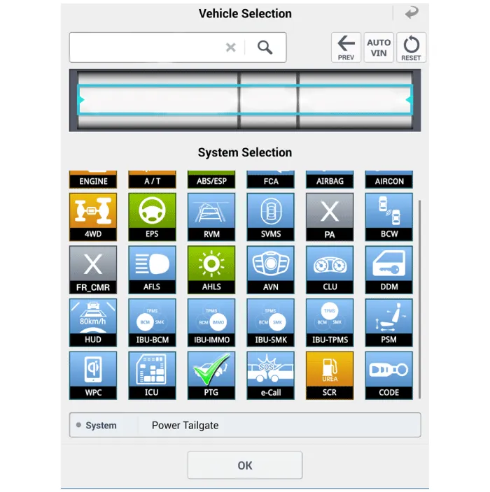
3.Check the sensor data.
 Components and Components Location
- Component Location
1. Buzzer2. Liftgate open switch (Crsah pad lower switch)3. Fob key4. Spindle Drive (2EA)5. Liftgate inner switch6. Power Latch7. PTG Control Module
Liftgate Inner Switch
...
 Troubleshooting
- Failure Inspection
Diagnosis with diagnostic tool
1.In the body electrical system, failure can be quickly diagnosed by
using the vehicle diagnostic system (diagnostic tool).The diagnostic
sy ...
Other information:
Hyundai Tucson (NX4) 2022-2026 Service Manual: CVVT (Continuously Variable Valve Timing) System
- Description
Continuous Variable Valve Timing (CVVT) system advances or retards the
valve timing of the intake and exhaust valve in accordance with the ECM
control signal which is calculated by the engine speed and load.By
controlling CVVT, the valve over-lap or under-lap occurs, which mak ...
Hyundai Tucson (NX4) 2022-2026 Owner's Manual: Distance to empty
The distance to empty is the estimated
distance the vehicle can be driven with
the remaining fuel.
If the estimated distance is below 1 mile
(1 km), the trip computer displays “---” as
the distance to empty. When this occurs,
refuel the vehicle immediately.
Information
The dist ...
