Hyundai Tucson: Engine Control System / Injector
| Item | Specification |
| Coil Resistance (Ω) | 11.4 - 12.6 |
| Item | Specification |
| Coil Resistance (Ω) | 1.43 - 1.58 |
1.In the engine control system, failure can be quickly diagnosed by using the diagnosis tool.
(1)Self diagnosis : Checking failure and code number (DTC).
(2)Current data : Checking the system input/output data state.
(3)Actuation test : Checking the system operation condition.
(4)Additional function : Controlling other features including system option setting and zero point adjustment.
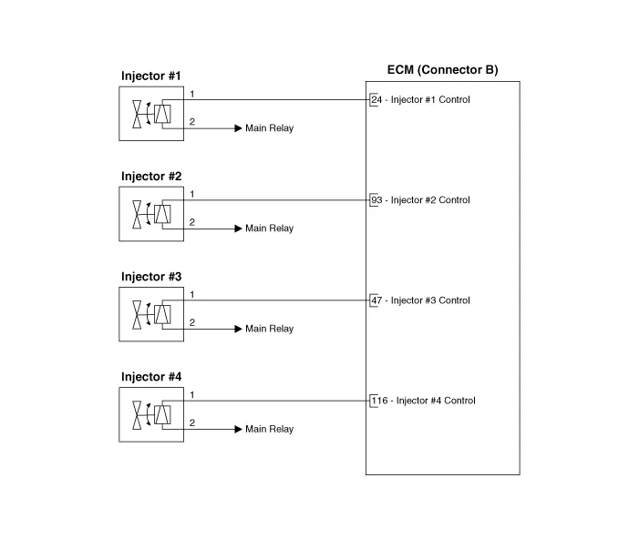
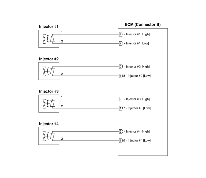
1.Turn the ignition switch OFF.
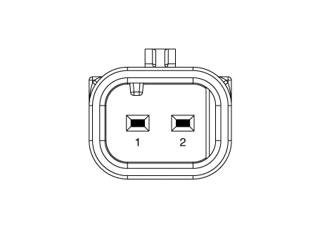
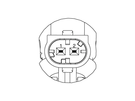
2.Disconnect the injector connector.
3.Check that the resistance is within the specification.
Specification : Refer to "Specification"
1.Release the residual pressure in fuel line.(Refer to Fuel Delivery System - "Release Residual Pressure in Fuel Line")
2.Turn the ignition switch OFF and disconnect the battery negative (-) cable.
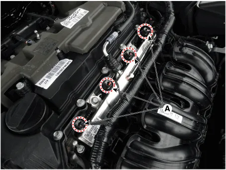
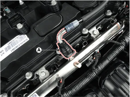
3.Disconnect the injector connector (A).
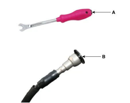
4.Disconnect the fuel feed quick-connector (A).
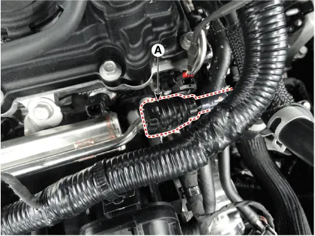

• Open the clamp cover (A) before disconnecting the quick-connector. (If the clip is applied)
• When removing the quick-connnector with the clip removing tool (A), be careful not to damage the plastic clip (B).
• If the clip is damaged, it can cause a fuel leak due to bad connection and could result in a fire.
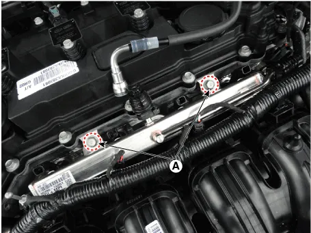
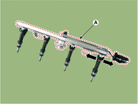
5.Remove the delivery pipe after loosening the mounting bolt (A).
Tightening Torque :18.6 - 23.5 N.m (1.9 - 2.4 kgf.m, 13.7 - 17.3 lb-ft)
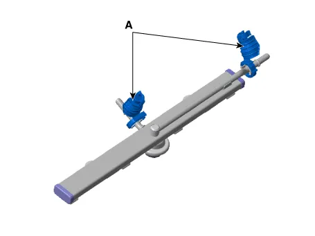
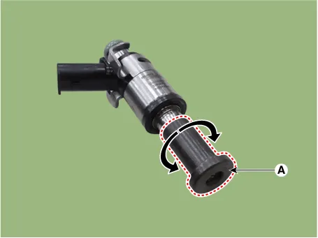
6.Remove the injector from the delivery pipe (A) after releasing the fixing clip both side as shown below.
1.Release the residual pressure in fuel line.(Refer to Fuel Delivery System - "Release Residual Pressure in Fuel Line")
2.Turn the ignition switch OFF and disconnect the battery negative (-) cable.
3.Remove the air cleaner assembly.(Refer to Engine Mechanical System - "Air Cleaner")
4.Remove the intake manifold.(Refer to Engnie Mechanical System - "Intake Manifold")
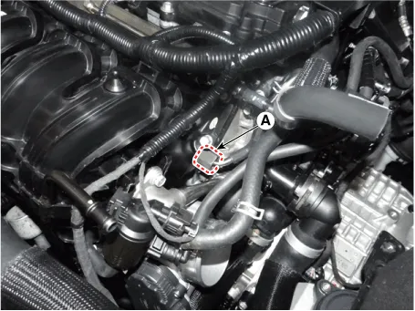
5.Remove the injector foam (A).
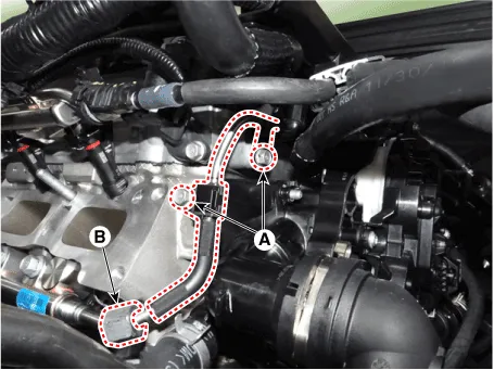
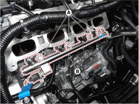
6.Loosen the high pressure fuel pipe bracket mounting bolt (A) and then loosen the flange nut (B,C).
Tightening Torque A : 9.8 - 11.8 N.m (1.0 - 1.2 kgf.m, 7.2 - 8.7 lb-ft)B, C : 26.5 - 32.4 N.m (2.7 - 3.3 kgf.m, 19.5 - 23.9 lb-ft)
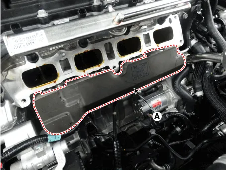
7.Loosen the mountin bolt (A) and then remove the delivery pipe & injector assembly (B).
Tightening Torque :18.6 - 23.5 N.m (1.9 - 2.4 kgf.m, 13.7 - 17.3 lb-ft)
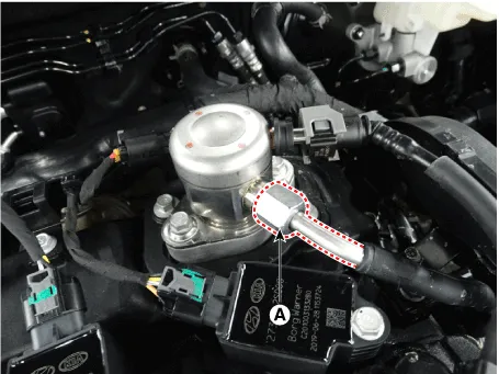
8.Disconnect the injector & rail pressure sensor connector (A).
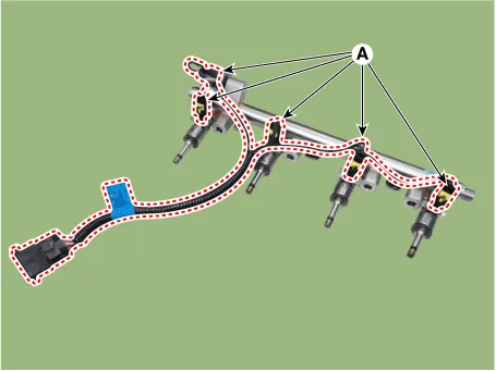
9.Remove the injector from the delivery pipe (A) after releasing the fixing clip both side as shown below.
1.Install in the reverse order of removal.

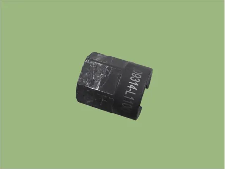
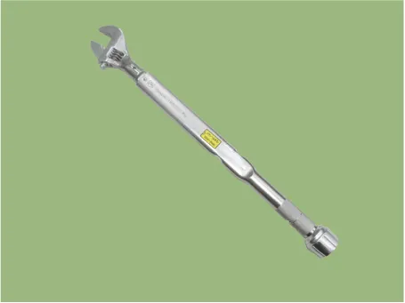
• When tightening the high pressure fuel pipe flenge nut (A), using a SST (SST No. : 09314-L1100).
• Using a spanner torque wrench (27mm).
• Do not reuse the high pressure fuel pipe.
• Note that do not deforming the high pressure fuel pipe.
• Install the component with the specified torques.
• Install the high pressure fuel pipe and then check the oil leakage.
• When Installing the high pressure fuel pipe, using a SST (SST No. : 09314-L1100).
(1)When reusing the injector refer to below.
• When removing/reinstalling the injector, clean the cylinder head hole and the appearance.(Removal of carbon deposits and foreign substances using a brush)
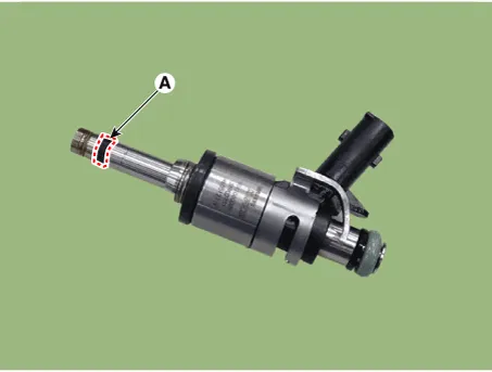
• Be careful not to apply oil/grease/lubricant to the combustion seal (A).
• Do not use the dropped part.
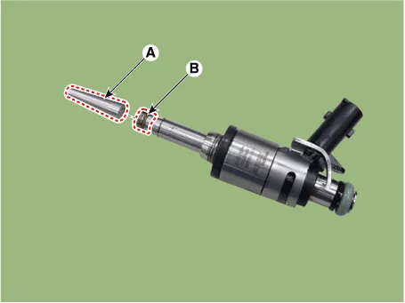
• When inserting the injector, be careful not to damage the injector tip.
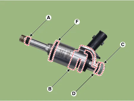
• Do not reuse the combustion seal (A), injector clip (B), O-ring (C), support disk (D), rubber washer (F).
• Be careful not to apply oil to combustion seal.
• Do not reuse the O-ring (A).
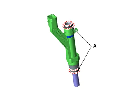
• Apply the engine oil to the injector O-ring.
• When inserting the injector, be careful not to damage the injector tip.

• In order to prevent from oil leak, replacement of combustion seal should follow the below procedure.
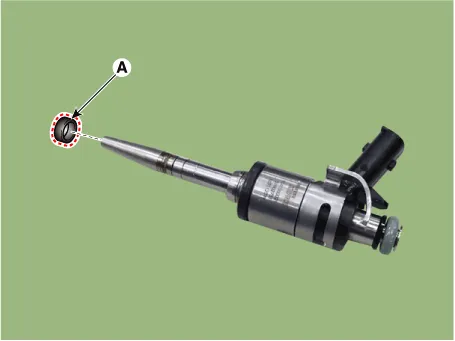
1.Remove the combustion seal (A).

• Be careful not to damage the injector while remove the combustion seal.
• Remove the combustion seal using a nipper.

2.Before the assembly of the sealing ring the groove must be cleaned using a clean cloth.
3.Install the combustion seal using a special service tool (SST No. :09353-L1100).
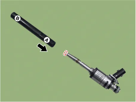
(1)Place the seal installing guide (A) (SST No.: 09353-2B000) on the tip of the injector not to damage the injector tip (B).
(2)Install the combustion seal (A) to the seal installing guide.
(3)Input the seal to A direction of the installer, and push it to B direction until it reaches the combustion seal installation area.

• The complete assembly must not take longer than 2 to 3 seconds.
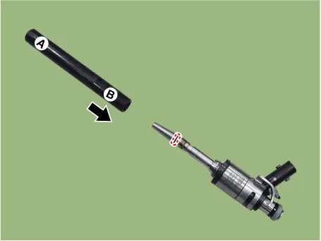
(4)Install the compressor (A) and disconnect it after rotating 3-4 times to left and right direction.
(5)Check the combustion seal (A) installation.

 Fuel Tank Pressure Sensor (FTPS)
- Description
Fuel Tank Pressure Sensor (FTPS) is a component of the evaporative
emission control system and is installed on the fuel tank, the fuel
pump, or the canister. It checks the purge c ...
 Purge Control Solenoid Valve (PCSV)
- Description
Purge Control Solenoid Valve (PCSV) is a solenoid valve and is
installed on the surge tank and controls the passage between the
canister and the intake manifold.The evaporative ga ...
Other information:
Hyundai Tucson (NX4) 2022-2026 Owner's Manual: If the Engine Overheats
If your temperature gauge indicates
overheating, you experience a loss of
power, hear loud pinging or knocking,
or the engine may be overheating. If this
happens, you must:
1. Pull off the road and stop as soon as it
is safe to do so.
2. Shift the gear to P (Park) and apply the
parking ...
Hyundai Tucson (NX4) 2022-2026 Service Manual: Schematic Diagrams
- System Block Diagram
Component Parts And Function Outline
Component partFunction
Vehicle-speed sensor, ESP/ABS Control ModuleConverts vehicle speed to pulse.
ECMReceives signals from sensor and control switches.
Cruise control indicatorIlluminate when CRUISE main switch is ON (Built into ...
