Hyundai Tucson: Button Engine Start System / Description and Operation
• Changing the state of engine ignition and power by using the start button.
• Controlling external relays for ACC / IGN1 / IGN2 terminal switching and STARTER, without use of mechanical ignition switch.
• Indicating the vehicle status on display by using LED or explicit messages.
• Immobilizer function by LF transponder communication between fob and fob holder.
• Interface with Low Speed CAN vehicle communication network.
1.Control Ignition and engine ON/OFF by Sending signal to IPM.
2.Display status by LED Lamp ON/OFF. (Amber or Green)
1.Electric power ON / Ignition ON
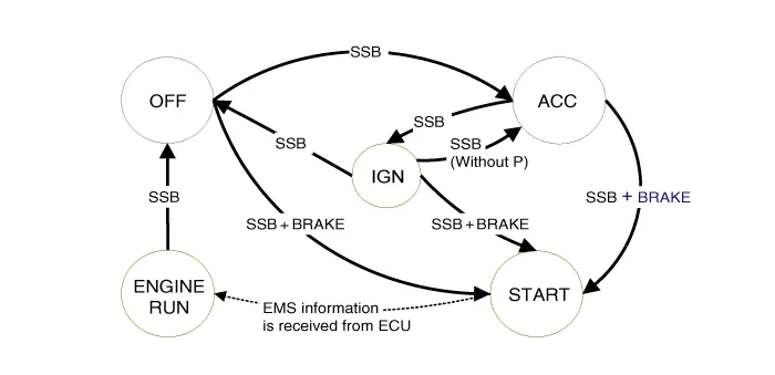
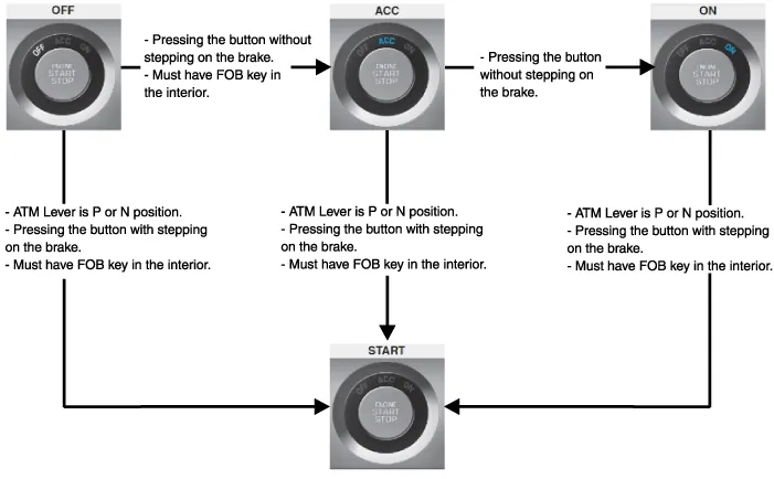
– The electric power state changes within the range of OFF →ACC→IGN→OFF by pressing the button without stepping on the brake (Or with stepping on the brake) inside the car with FOB key (However, When the gear is not in P, the power repeatedly changes between ACC and IGN. Converting to OFF is impossible.)
– The ignition is on when the button is pressed with stepping on the brake at P/N position with FOB key.
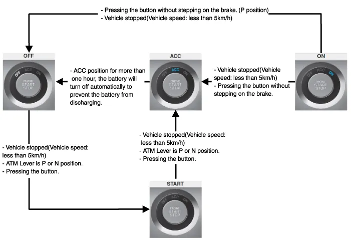
2.Electric power OFF/ Ignition OFF
– The ignition OFF is possible in the state of vehicle stop. (The ignition OFF state is possible regardless of the ATM lever position.)
– The lever shall be shifted for parking in gear N by pressing the ATM lever release button after electric power off in P.
3.How to off the ignition forcibly and to restart during driving
– It is a method of forcibly turning off ignition in case of fuel leakage when the vehicle is overturned or of emergency (e.g. failure in accelerator pedal return)
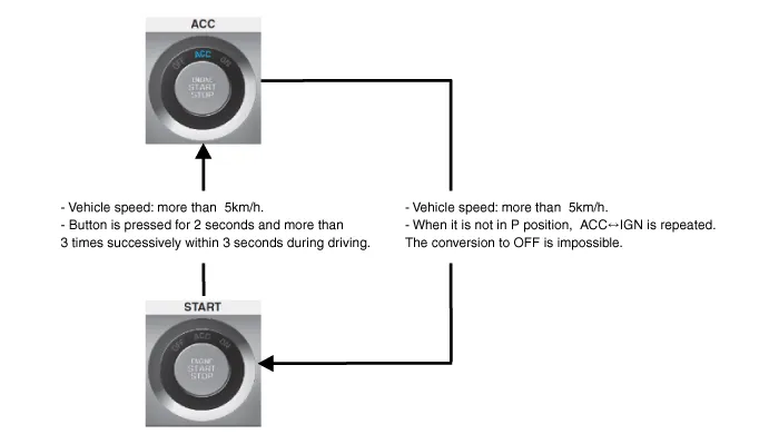
– The engine is off and returned to the ACC state when the button is pressed for 2 seconds and more than 3 times successively within 3 seconds during driving. The restarting is available for next 30 seconds regardless of FOB key and the electric power is changed through OFF → ACC→IGN→OFF by pressing the button without stepping on the brake (or with stepping on the brake) inside the car with FOB key. (However, when it is not in P position, ACC↔IGN is repeated. The conversion to OFF is impossible.)
4.State of start button indicator (LED) ON depending on the electric power state.
– Electric power OFF : LED OFF
– Electric power ACC state : Yellow LED ON
– Electric power ON : Blue LED ON
– During cranking : Maintaining the previous LED ON state before cranking
– Starting ON state : LED OFF
• Switching of ACC / IGN1 / IGN2 terminals.
• Control of the STARTER relay BAT line (high side) based on communication with EMS ECU.
• Management of the Immobilizer function.
• Management of BES warning function.
• "Start Stop Button (SSB) monitoring",
• "Immobilizer communication" (with Engine Management System unit for immobilizer release)
• "Authentication server" (Validity of Transponder and in case of Smart Key option Passive Fob authentication )
• "System consistency monitoring"
• "System diagnosis"
• Control of display message / warning buzzer
The smart key unit masters the entire button engine start system.In case of SMART KEY application, for example "Passive Access", "Passive Locking" and "Passive Authorization are integrated for Terminal switching Operations".It collects information about vehicle status from other modules (vehicle speed, alarm status, driver door open...), reads the inputs (e.g. SSB, Capacitive Sensor / Lock Button, PARK position Switch), controls the outputs (e.g. exterior and interior antennas), and communicates with others devices via the CAN network as well as a single-line interfaces.The diagnosis and learning of the components of the BES System are also handled by the SMK.The SMK manages the functions related to the "terminal control" by activating external relays for ACC, IGN1 and IGN2. This unit is also responsible for the control of the STARTER relay.The SMK is also controlling the illumination of the SSB as well as the "system status indicator", which consists of 2 LEDs of different color. The illumination of the fob holder is also managed by the SMK.The SMK reads the inputs (Engine fob in, vehicle speed, relays contact status), controls the outputs (Engine relay output drive), and communicates with others devices via the CAN.The internal architecture of the SMK is defined in a way that the control of the terminal is secured even in case of failure of one of the two microcontrollers, system inconsistency or interruption of communication on the CAN network.In case of failure of one of the two controllers, the remaining controller shall disable the starter relay. The IGN1 and IGN2 terminals relays shall be maintained in the state previously memorized before the failure and the driver shall be able to switch those IGN terminals off by pressing the SSB with EMERGENCY_STOP pressing sequence. However, engine restart will not be allowed. The state of the ACC relay will depend on the type of failure.The main functions of the SMK are :• Control of Terminal relays
• Monitoring of the Vehicle speed received from sensor or ABS/ESP ECU.
• Control of SSB LEDs (illumination, clamp state).
• Control of the base station located in SSB through direct serial interface.
• System consistency monitoring to diagnose SMK failure and to switch to relevant limp home mode.
• Providing vehicle speed information
• Start Stop Button (SSB) monitoring
• Starter power control
• To activate the power modes ‘Off’, ’Accessory’, ‘Ignition’ and 'Start' by switching the corresponding terminals
• To start the engine
• To stop the engine
The contact will be insured by a micro-switch and a backlighting is provided to highlight the marking of the button whenever necessary.Three (3) LED colors are located in the outside ring of the switch assy. They display the status of the system.They are OFF(White) / ACC(Amber) / ON(Green).| System State | Terminal Status | Engine status |
| 1. OFF - Locked | OFF | Stopped |
| 2. OFF - Unlocked | OFF | Stopped |
| 3. ACC | ACC | Stopped |
| 4. IGN | IGN1, IGN2, ACC | Stopped |
| 5. Start | IGN1, Start | Cranking |
| 6. IGN - Engine | IGN1, IGN2, ACC | Running (means "self-running") |
Referring to the terminals, the system states described in the table above are the same as those found in a system based on a mechanical ignition switch.One of the features distinctive from the Mechanical Ignition Switch-based system is that the BES system allows specific transition from [OFF] to [START] without going through [ACC] and [IGN] states.
| System State | Terminal Status | Engine status |
| 1. OFF - UNLOCKED | OFF | Stopped |
| 2. ACC | ACC | Stopped |
| 3. IGN | IGN1, IGN2, ACC | Stopped |
| 4. Start | IGN1, START with special pattern of activation | Cranking |
| 5. IGN - Engine | IGN1, IGN2, ACC | Running (means "self-running") |
Referring to the terminals, the system states described in the table above are the same as those found in a system based on a mechanical ignition switch.One of the features distinctive from the Mechanical Ignition Switch-based system is that the BES system allows specific transition from [OFF] to [START] without going through [ACC] and [IGN] states.

 Components and Components Location
- Component Location
1. Start Stop Button(SSB)2. FOB Key3. Liftgate open button4. Interior antenna 15. Interior antenna 26. Intergrated Body Control Unit (IBU)7. Liftgate antenna8. Door handle & ...
Other information:
Hyundai Tucson (NX4) 2022-2026 Service Manual: Sunroof Assembly
- Components Location
1. Sunroof assembly
- Replacement
• When removing with a flat - tip screwdriver or remover, wrap
protective tape around the tools to prevent damage to components.
• Put on glove to protect your hands.
1.Remove the roof trim.(Refer to ...
Hyundai Tucson (NX4) 2022-2026 Owner's Manual: Rear Window Wiper and Washer
The rear window wiper and washer
switch is located at the end of the wiper
and washer switch lever. Turn the switch
to the desired position to operate the
rear wiper and washer.
HI – High wiper speed
LO – Low wiper speed
OFF – Off
Push the lever away from you to spray
rear ...
