Hyundai Tucson: Exhaust Emission Control System / CVVT (Continuously Variable Valve Timing) System
– the CVVT Oil Control Valve (OCV) which supplies the engine oil to the cam phaser or takes out the engine oil from the cam phaser in accordance with the ECM PWM (Pulse With Modulation) control signal,
– the CVVT Oil Temperature Sensor (OTS) which measures the engine oil temperature,
– and the Cam Phaser which changes the cam phase by using the hydraulic force of the engine oil.
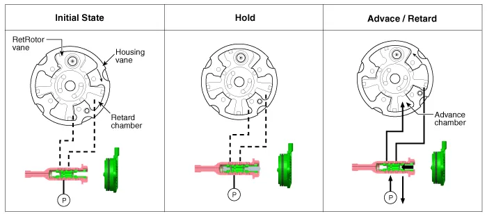
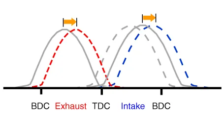
The engine oil which is supplied from the CVVT oil control valve changes the cam phase in the direction (Intake Advance/Exhaust Retard) or opposite direction (Intake Retard/Exhaust Advance) of the engine rotation by rotating the rotor connected with the camshaft inside the cam phaser.
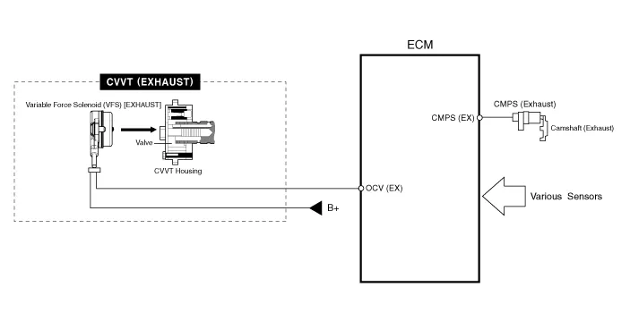

• The variable force solenoid (VFS) changes its force depending on the PWM duty to control the stroke of the OCV.
• It also controls the lock, unlock, advanced, retarded, and holding functions.
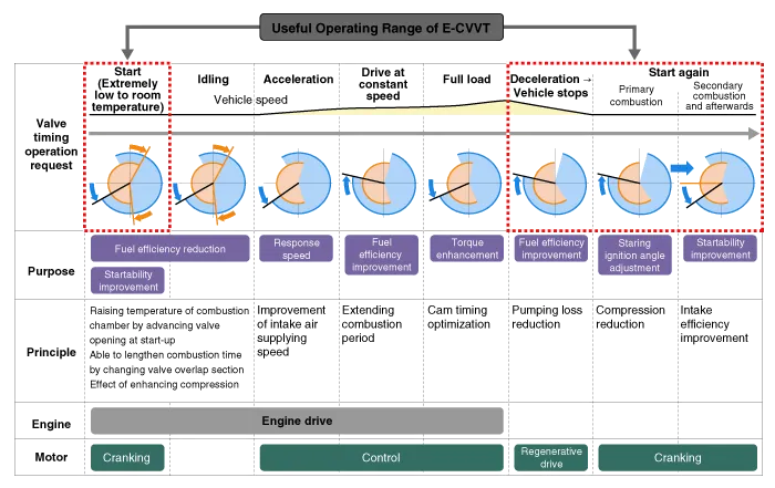
[CVVT System Mode]
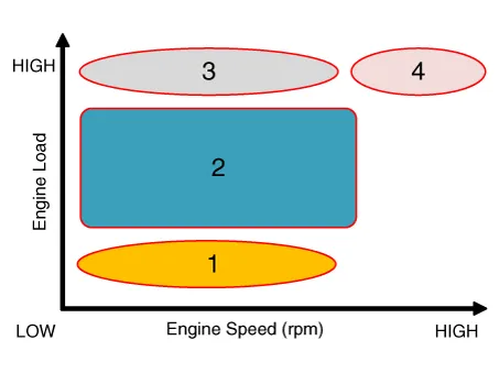
| (1) Low Speed / Low Load | (2) Part Load |
|
|
| (3) Low Speed / High Load | (4) High Speed / High Load |
|
|
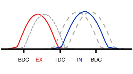
| Driving Condition | Exhaust Valve | Intake Valve | ||
| Valve Timing | Effect | Valve Timing | Effect | |
| (1) Low Speed/Low Load | Completely Advance | * Valve Under-lap * Improvement of combustion stability | Middle | * Valve Under-lap * Improvement of combustion stability |
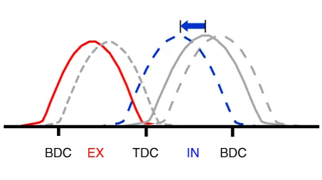
| (2) Part Load | Retard | * Reduction of HC | Retard | * Reduction of pumping loss |
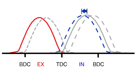
| (3) Low Speed /High Load | Completely Advance | * Reduction of pumping loss | Advance | * Prevention of intake back flow (Improvement of volumetric efficiency) |
| (4) High Speed/High Load | Completely Advance | * Reduction of pumping loss | Advance | * Prevention of intake back flow (Improvement of volumetric efficiency) |
 Catalytic Converter
- Description
The catalytic converter of the gasoline engine is a three way catalyst.
It oxidizes carbon monoxide and hydrocarbons (HC), and separates oxygen
from the oxides of nitrogen (NOx).
...

Other information:
Hyundai Tucson (NX4) 2022-2026 Owner's Manual: Auto Defogging System
on Models with Automatic
Temperature Control
Auto defogging reduces the likelihood of
fogging up the inside of the windshield
by sensing moisture on the inside of the
windshield.
The auto defogging system operates
when the heater or air conditioning is on.
Information
The Auto Defogging system may not
operate normally, when the ...
Hyundai Tucson (NX4) 2022-2026 Service Manual: Components and Components Location
- Components
1. RH water jacket insert2. LH water jacket insert3. Cylinder block4. O-ring5. Piston cooling oil jet6. Crankshaft upper bearing (No. 1, 5 journal)7. Thrust bearing8. Crankshaft upper bearing (No. 2, 3, 4 journal)9. Crankshaft10. Crankshaft position sensor wheel11. Crankshaft lowe ...
