Hyundai Tucson: Audio / Audio Unit
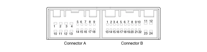
| No | Connector A | Connector B |
| 1 | Rear left speaker (+) | MM_CAN (HIGH) |
| 2 | Front left speaker (+) | - |
| 3 | Front right speaker (+) | - |
| 4 | Rear right speaker (+) | Steering wheel remote |
| 5 | - | - |
| 6 | Door open | USB D (+) |
| 7 | IGN 1 | USB VOC |
| 8 | Illumination (+) | - |
| 9 | - | - |
| 10 | Rear left speaker (-) | MIC (+) |
| 11 | Front left speaker (-) | ACC |
| 12 | Front right speaker (-) | Battery (+) |
| 13 | Rear right speaker (-) | MM_CAN (LOW) |
| 14 | - | - |
| 15 | - | - |
| 16 | - | Vehicle Speed |
| 17 | Illumination (-) | Steering wheel remote GND |
| 18 | - | USB D (-) |
| 19 | USB GND | |
| 20 | - | |
| 21 | - | |
| 22 | MIC (-) | |
| 23 | - | |
| 24 | GND |
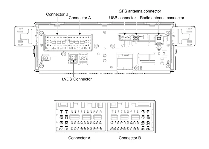
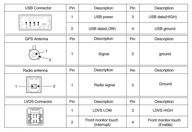
| Pin | Connector A | Connector B |
| 1 | Rear left door speaker (+) | - |
| 2 | Rear left door speaker (-) | Mic (+) |
| 3 | - | - |
| 4 | - | - |
| 5 | Keyboard reset | - |
| 6 | Camera power | Illumination (+) |
| 7 | Camera video | M-CAN (High) |
| 8 | - | - |
| 9 | - | - |
| 10 | - | Battery (+) |
| 11 | USB DETECT | Battery (+) |
| 12 | Steering wheel remote | Ground |
| 13 | Front left door speaker (+) | Ground |
| 14 | Front left door speaker (-) | - |
| 15 | Front right door speaker (-) | Mic (-) |
| 16 | Front right door speaker (+) | Camera equipment detect2 |
| 17 | - | - |
| 18 | - | - |
| 19 | - | Illumination (-) |
| 20 | Camera power ground | M-CAN (Low) |
| 21 | Camera video ground | - |
| 22 | - | ACC |
| 23 | - | Keyboard power |
| 24 | - | Front monitor power |
| 25 | - | - |
| 26 | Steering wheel remote ground | - |
| 27 | Rear right door speaker (-) | - |
| 28 | Rear right door speaker (+) | - |
| 29 | - | - |
| 30 | - | - |
| 31 | - | - |
| 32 | Camera equipment Detect1 | - |
| 33 | - | IGN 1 |
| 34 | - | Keyboard ground |
| 35 | - | Front monitor ground |
| 36 | - | |
| 37 | - | |
| 38 | Vehicle Speed |
1.Disconnect the negative (-) battery terminal.
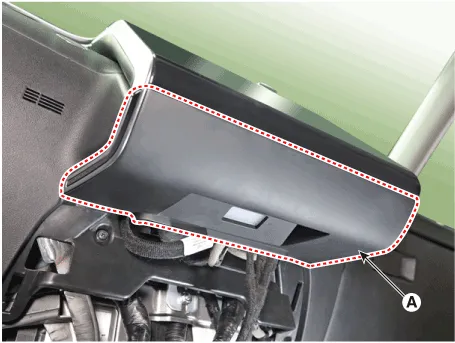
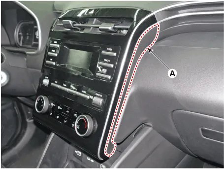
2.Remove the front monitor lower cover (A).

3.Remove the front monitor lower cover after disconnecting the mood lamp connector (A).

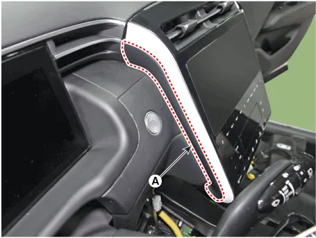
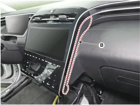
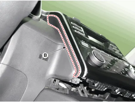
4.Remove front monitor side cover (A) and (B).
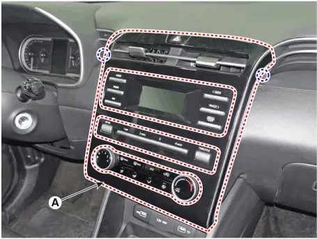
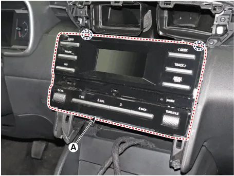
5.Remove the front monitor assembly (A).
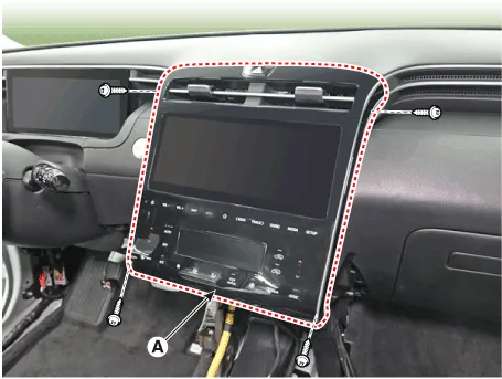
6.Remove the front monitor assembly (A) after disconnecting monitor connectors.
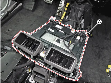
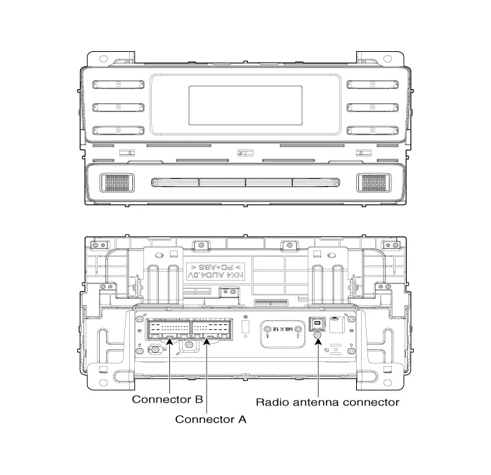
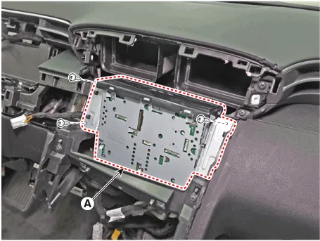
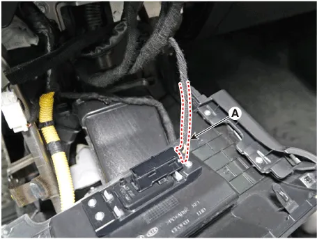
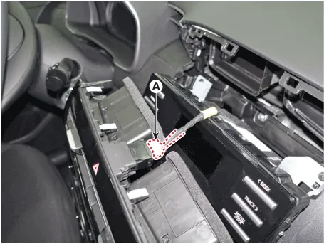
7.Remove the audio unit (A) after loosening mounting screws.
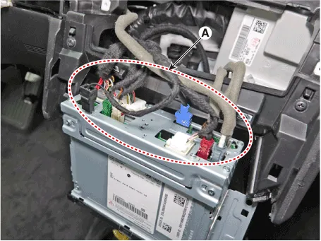
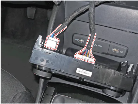
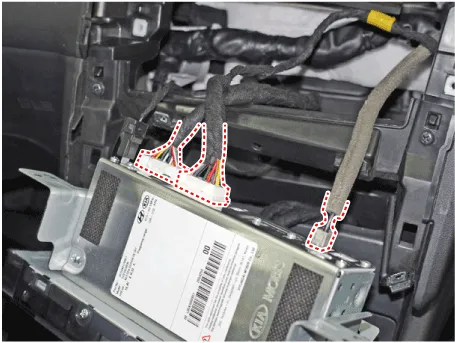
8.Remove the audio unit after disconnect audio connectors (A).
1.Disconnect the negative (-) battery terminal.
2.Remove the front monitor lower cover (A).
3.Remove the front monitor lower cover (A) after disconnecting the mood lamp connector (A).
4.Remove front monitor side cover (A) and (B).
5.Remove the front monitor cover (A) after loosening mounting screws.
6.Remove the Front monitor cover after disconnect the hazard switch connector (A).
7.Remove the heater control unit (A) after loosening mounting screws.
8.Remove the heater control unit after disconnecting connectors.
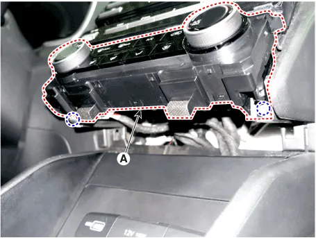
9.Remove the audio unit (A) after loosening mounting screws.
10.Remove the audio unit after disconnecting connectors.
1.Install audio connectors and antenna connectors.
2.Install the audio unit.
3.Install the front monitor assembly.
4.Install the front monitor side cover.
5.Install the front monitor lower cover.
6.Connect the negative (-) battery terminal.

• Make sure the connector are connected in properly.
• Check the audio system for normal operation.
1.Install audio connectors and antenna connectors.
2.Install the audio unit.
3.Install the front monitor assembly.
4.Install the front monitor cover.
5.Install the front monitor side cover.
6.Install the front monitor lower cover.
7.Connect the negative (-) battery terminal.
 Specifications
- Specifications
Audio Unit
ItemSpecification
Power supplyDC 14.4V
Parasitic currentMax. 40W X 4
Impedance4 Ω x 4
Antenna80PF 75Ω
Tuning typePLL synthesized type
Frequency range /Channel s ...
 Speakers
- Inspection
1.Check the plus (+) and negative (-) speaker terminals using an ohmmeter.
2.Check the supply power to the speaker and the resistance, then inspect the sound quality.
- Removal
...
Other information:
Hyundai Tucson (NX4) 2022-2026 Owner's Manual: Surround View Monitor
Malfunction and Limitations
Surround View Monitor malfunction
When Surround View Monitor is not
working properly, or the screen flickers,
or the camera image does not display
normally, have the vehicle inspected by
an authorized HYUNDAI dealer.
Limitations of Surround View
Monitor
When your vehicle is stopped
...
Hyundai Tucson (NX4) 2022-2026 Owner's Manual: System Operation
Ventilation
1. Set the mode to the position.
2. Set the air intake control to the
outside (fresh) air position.
3. Set the temperature control to the
desired position.
4. Set the fan speed control to the
desired speed.
Heating
1. Set the mode to the position.
2. Set the air intake con ...
