Hyundai Tucson: Parking Distance Warning (PDW) / Description and Operation
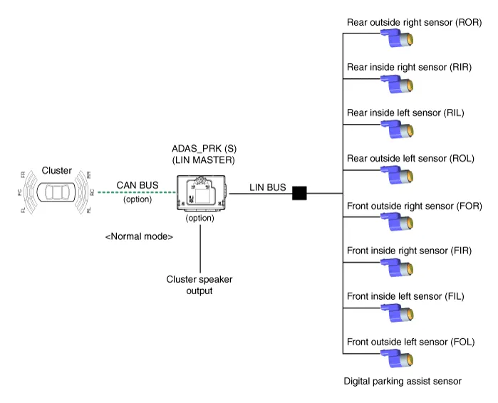
• PDW consists of 8 sensors (front : 4 units, rear : 4 units) that are used to detect obstacles and transmit the result in three separate warning levels, the first, second and third to IBU via LIN communication.
• IBU decides the alarm level by the transmitted communication message from the slave sensors, then operates the buzzer or transmits the data for display.
Initial mode
1.System initializing time
– PDW-F : 500ms after IGN1+ initial D Gear + below 10 Km/h
– PDW-R : 500ms after IGN1+ initial R Gear
2.PDW recognizes LID and sets the sensor ID up during initialization.
3.PDW activates each sensor and then executes the diagnosis after finishing initialization of IPM(IBU).
4.PDW starting buzzer is normally worked, when sensor does not send an error message and after finishing error diagnosis.
5.If any failure is received from the any sensors, PDW starting buzzer does not work but the failure alarm is operated for a moment.If you have display option, warning sign is also shown on it.

6.IBU memorizes the completed initializing status of sensor.
Normal mode
1.PDW-F : Lin communication starts and keeps the routine after IGN1 ON+D gear + below 10 km/h. PDW-R : Lin communication starts and keeps the routine after IGN1 ON+R gear
2.After initializing, the routine starts at once without PDW starting warning sound.
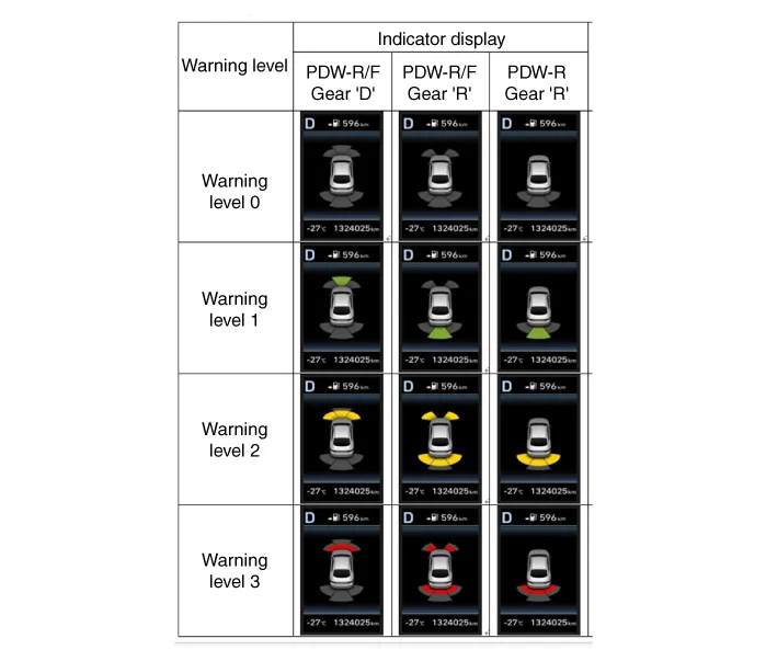
3.Alarms of obstacle consists of 3 level 1,2,3 step and 1,2 alarm sounds intermittently and 3 alarm sounds continuously. 1 level alarm doesn't exist in the front ultrasonic sensor.
4.In display, the data of each sensor is sent from IBU to display, for example cluster. CAN communication is used for transmission and maximum gateway time is 50ms.
5.The efficient vehicle speed of PDW operation is under 10Km/h.
6.Operation doesn't start or stops at gear N, P.
| Level | Distance range | Allowed range |
| 1 | Front : 61 - 100 cm (24.02 - 39.37 in.) / Rear : 61 - 120 cm (24.02 - 47.2 in.) | ± 15 cm (5.90 in.) |
| 2 | 31 - 60 cm (12.20 - 23.62 in.) | ± 15 cm (5.90 in.) |
| 3 | 0 - 30 cm (0 - 11.81 in) | ± 10 cm (3.94 in.) |
*Measurement condition : PVC pipe - Diameter 75 mm (0.0394 in.), length 1 m (39.37 in.), at normal temperature

 Components and Components Location
- Component Location
1. ADAS_PRK (S)2. Ultrasonic Sensor
※ PDW function is applied alone, it is integrated into ADAS_PRK (S) ...
Other information:
Hyundai Tucson (NX4) 2022-2026 Service Manual: Joint Assembly (Transaxle side)
- Removal
• Drive shaft joints require special grease, so do not add any other type of grease.
• When replacing the boot band, it must be a new one.
1.Remove the front drive shaft.(Refer to Driveshaft Assembly - "Front Driveshaft")
2.Remove the transaxle side large ...
Hyundai Tucson (NX4) 2022-2026 Owner's Manual: Downhill Brake Control (DBC)
indicator light
This indicator light illuminates:
When the ignition switch is in the ON
position. The downhill brake control
indicator light illuminates for about 3
seconds and then goes off.
When you activate the system by
pressing the DBC button.
This indicator light blinks:
When Downhill ...
